Clamped inductive switching protects your circuit from voltage spikes by using a diode or snubber to safely dissipate the energy stored in the inductor, while unclamped switching allows these spikes to occur, risking component damage. Explore the rest of the article to understand the advantages and considerations of each method for your applications.
Table of Comparison
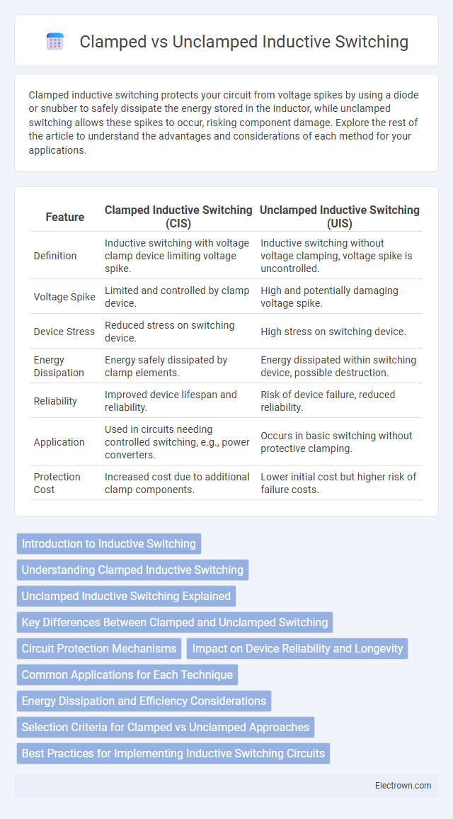
| Feature | Clamped Inductive Switching (CIS) | Unclamped Inductive Switching (UIS) |
|---|---|---|
| Definition | Inductive switching with voltage clamp device limiting voltage spike. | Inductive switching without voltage clamping, voltage spike is uncontrolled. |
| Voltage Spike | Limited and controlled by clamp device. | High and potentially damaging voltage spike. |
| Device Stress | Reduced stress on switching device. | High stress on switching device. |
| Energy Dissipation | Energy safely dissipated by clamp elements. | Energy dissipated within switching device, possible destruction. |
| Reliability | Improved device lifespan and reliability. | Risk of device failure, reduced reliability. |
| Application | Used in circuits needing controlled switching, e.g., power converters. | Occurs in basic switching without protective clamping. |
| Protection Cost | Increased cost due to additional clamp components. | Lower initial cost but higher risk of failure costs. |
Introduction to Inductive Switching
Inductive switching involves controlling current flow through an inductor, which generates voltage spikes due to energy stored in the magnetic field when the current is interrupted. Clamped inductive switching uses components like flyback diodes to safely redirect this energy, preventing damage to circuit elements and minimizing electromagnetic interference. Unclamped switching lacks such protective measures, often resulting in higher voltage transients that can stress or damage your electronic components.
Understanding Clamped Inductive Switching
Clamped inductive switching involves controlling the voltage spike generated when an inductive load is switched off, using components like diodes or snubbers to limit voltage stress. This technique protects switching devices from high voltage transients by providing a path for the inductive current, ensuring device reliability and longevity. Understanding clamped inductive switching is crucial for designing circuits with inductive loads to prevent damage and improve overall system stability.
Unclamped Inductive Switching Explained
Unclamped inductive switching occurs when an inductive load, such as a coil or motor winding, is switched off without any protective snubber or clamp circuit, causing a high-voltage spike due to the sudden interruption of current. This voltage spike, governed by the inductor's stored energy and the rapid change in current, can exceed device voltage ratings, leading to potential damage or failure in switching components like transistors or MOSFETs. Understanding unclamped inductive switching is crucial for designing robust circuits that mitigate voltage transients through proper snubber circuits or clamp devices to enhance reliability.
Key Differences Between Clamped and Unclamped Switching
Clamped inductive switching uses a voltage clamp or snubber circuit to limit the voltage spike generated when interrupting current through an inductor, protecting components from high-voltage transients. Unclamped switching allows the voltage spike to rise freely, often causing severe voltage overshoot and potential damage to switches and insulation. Clamped switching enhances reliability and reduces electromagnetic interference, while unclamped switching demands robust voltage-rated components to withstand the transient stress.
Circuit Protection Mechanisms
Clamped inductive switching employs components like flyback diodes or transient voltage suppressors to limit voltage spikes and protect circuits from damaging overvoltages. Unclamped inductive switching lacks such protective elements, resulting in higher voltage transients that can stress semiconductor devices and degrade circuit reliability. Effective circuit protection mechanisms in clamped configurations improve device longevity and minimize electromagnetic interference caused by inductive loads.
Impact on Device Reliability and Longevity
Clamped inductive switching reduces voltage spikes by limiting the peak voltage across the device, significantly enhancing device reliability and extending component longevity through controlled energy dissipation. Unclamped inductive switching exposes the device to high voltage transients, increasing the risk of insulation breakdown and accelerated wear, thus compromising long-term operational stability. Employing clamped circuits such as snubbers or freewheeling diodes mitigates destructive voltage stress, optimizing device lifetime in inductive load switching applications.
Common Applications for Each Technique
Clamped inductive switching is commonly used in power electronics for protecting components in circuits such as motor drives and DC-DC converters by limiting voltage spikes during switching events. Unclamped inductive switching frequently occurs in applications like relay or contactor switching where voltage transients are less controlled but acceptable due to the robustness of the system. Industrial automation and automotive electronics benefit from clamped switching to enhance device reliability, while unclamped switching remains prevalent in simpler, cost-sensitive designs.
Energy Dissipation and Efficiency Considerations
Clamped inductive switching significantly reduces energy dissipation by redirecting the inductive kick to a clamping device, minimizing voltage spikes and enhancing circuit efficiency. Unclamped switching, however, results in higher energy loss as the stored magnetic energy dissipates through the switching device, causing increased thermal stress and reduced system reliability. Efficient energy management in clamped configurations improves overall system longevity and maintains optimal performance in power electronics applications.
Selection Criteria for Clamped vs Unclamped Approaches
Selection criteria for clamped versus unclamped inductive switching hinge on controlling voltage spikes and managing energy dissipation. Clamped switching is preferred when precise voltage limitation is critical, protecting components from overvoltage by safely dissipating stored inductive energy through elements like snubbers or clamps. Unclamped switching suits applications prioritizing simplicity and efficiency, tolerating higher voltage overshoot but requiring robust devices capable of withstanding transient spikes without external voltage control.
Best Practices for Implementing Inductive Switching Circuits
Implementing inductive switching circuits requires careful consideration of clamped versus unclamped configurations to protect components from voltage spikes caused by inductive loads. Using a clamped inductive switch with a flyback diode or snubber circuit mitigates voltage transients, enhancing reliability and extending the lifespan of your switching devices. Ensuring proper component ratings and layout techniques minimizes electromagnetic interference and improves overall circuit performance.
Clamped vs Unclamped inductive switching Infographic