MOS capacitors feature a metal-oxide-semiconductor structure primarily used to characterize interface properties and oxide thickness, while MIS capacitors incorporate a metal-insulator-semiconductor stack allowing for a broader range of insulator materials and applications. Understanding the differences between these capacitor types can help optimize your semiconductor device design; explore the article to learn more about their distinct advantages and applications.
Table of Comparison
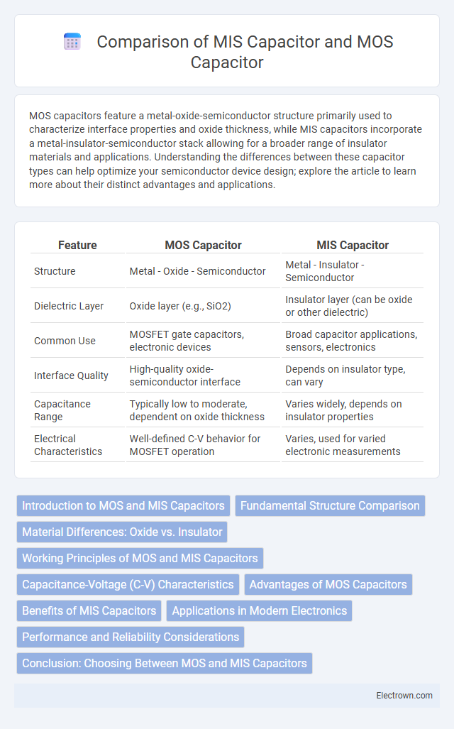
| Feature | MOS Capacitor | MIS Capacitor |
|---|---|---|
| Structure | Metal - Oxide - Semiconductor | Metal - Insulator - Semiconductor |
| Dielectric Layer | Oxide layer (e.g., SiO2) | Insulator layer (can be oxide or other dielectric) |
| Common Use | MOSFET gate capacitors, electronic devices | Broad capacitor applications, sensors, electronics |
| Interface Quality | High-quality oxide-semiconductor interface | Depends on insulator type, can vary |
| Capacitance Range | Typically low to moderate, dependent on oxide thickness | Varies widely, depends on insulator properties |
| Electrical Characteristics | Well-defined C-V behavior for MOSFET operation | Varies, used for varied electronic measurements |
Introduction to MOS and MIS Capacitors
MOS capacitors consist of a metal-oxide-semiconductor structure commonly used in semiconductor devices, where the oxide layer serves as the dielectric between the metal gate and the semiconductor substrate. MIS capacitors, which stand for metal-insulator-semiconductor capacitors, extend the MOS concept by allowing different insulating materials beyond just oxides, enhancing performance in various applications. Your understanding of these capacitors is crucial for optimizing device characteristics like capacitance, leakage current, and overall reliability in integrated circuits.
Fundamental Structure Comparison
The fundamental structure of a MOS capacitor consists of a metal gate, an oxide insulating layer, and a semiconductor substrate, forming a simple Metal-Oxide-Semiconductor interface primarily used for studying capacitance-voltage characteristics. In contrast, an MIS capacitor replaces the metal gate with a metal or polysilicon gate material and incorporates an insulator layer that can be an oxide, nitride, or a combination, enabling more complex interface engineering and enhanced device functionality. Both structures serve as critical components for understanding charge distribution, interface states, and device reliability, but MIS capacitors offer greater flexibility in material selection and interface control.
Material Differences: Oxide vs. Insulator
MOS capacitors utilize a thin oxide layer, typically silicon dioxide, as the dielectric material, providing excellent interface quality and electronic properties essential for semiconductor devices. MIS capacitors employ a broader range of insulator materials, such as silicon nitride or high-k dielectrics, enhancing capacitance and enabling improved device performance in advanced applications. Your choice between MOS and MIS capacitors depends on the required dielectric properties and integration compatibility with the semiconductor process.
Working Principles of MOS and MIS Capacitors
MOS capacitors operate by forming an inversion layer at the semiconductor-oxide interface when a voltage is applied, modulating the charge in the semiconductor substrate and enabling capacitance variation. MIS capacitors extend this principle by incorporating a metal-insulator-semiconductor structure, where the insulating layer separates the metal gate from the semiconductor, allowing control over surface charge through the insulator's properties. Understanding these working principles helps you optimize device performance in applications such as sensors, memory devices, and MOSFET gate structures.
Capacitance-Voltage (C-V) Characteristics
The MOS capacitor exhibits strong capacitance-voltage (C-V) characteristics with a well-defined accumulation, depletion, and inversion region, allowing precise analysis of oxide thickness and doping concentration. In comparison, the MIS capacitor includes an additional insulating layer that alters the C-V profile by introducing interface states and fixed charges, impacting its flatband voltage and threshold behavior. Understanding your device's C-V characteristics is critical for optimizing performance in semiconductor and sensor applications.
Advantages of MOS Capacitors
MOS capacitors offer superior voltage handling and lower leakage currents compared to MIS capacitors, enhancing device reliability in integrated circuits. Their well-defined oxide thickness provides consistent capacitance, crucial for precise analog and digital applications. The MOS structure also facilitates easy integration with CMOS technology, supporting scalable fabrication and improved device performance.
Benefits of MIS Capacitors
MIS capacitors offer enhanced insulation properties by incorporating an additional insulating layer, improving leakage current control compared to MOS capacitors. Their structure provides better reliability and stability in high-frequency applications, making them ideal for modern integrated circuits. You benefit from increased capacitance density and reduced power consumption with MIS capacitors, optimizing overall device performance.
Applications in Modern Electronics
MOS capacitors are widely used in digital integrated circuits for their role in threshold voltage control and charge storage, enabling efficient transistor operation in microprocessors and memory devices. MIS capacitors, incorporating a metal-insulator-semiconductor structure, find applications in high-frequency devices and sensors due to their improved interface quality and reduced leakage currents. Your choice between MOS and MIS capacitors can significantly impact device performance in applications such as RF circuits, analog signal processing, and advanced semiconductor sensors.
Performance and Reliability Considerations
MOS capacitors exhibit superior performance in high-frequency applications due to their well-defined oxide-semiconductor interface, which minimizes interface trap densities and enhances charge carrier mobility. MIS capacitors, incorporating an insulating layer between metal and semiconductor, offer improved reliability by reducing leakage currents and mitigating dielectric breakdown under high voltage stress. Both structures require careful control of oxide thickness and interface quality to optimize their electrical characteristics and ensure long-term stability in semiconductor device applications.
Conclusion: Choosing Between MOS and MIS Capacitors
Selecting between MOS and MIS capacitors depends on the application requirements, with MOS capacitors offering superior performance in high-frequency circuits due to their metal-oxide-semiconductor structure that provides low leakage current and high capacitance stability. MIS capacitors, featuring metal-insulator-semiconductor layers, excel in devices demanding enhanced dielectric properties and improved interface quality for advanced semiconductor technologies. Optimal capacitor choice hinges on balancing electrical characteristics, fabrication complexity, and integration with the specific semiconductor process in use.
MOS capacitor vs MIS capacitor Infographic