Ground loops occur when there are multiple ground paths causing interference and noise in audio or electrical systems, whereas signal ground refers to a single reference point for the return path of signals, designed to maintain signal integrity. Understanding the differences between ground loop and signal ground is essential for optimizing your system's performance, so explore the rest of the article to learn how to manage and prevent these issues effectively.
Table of Comparison
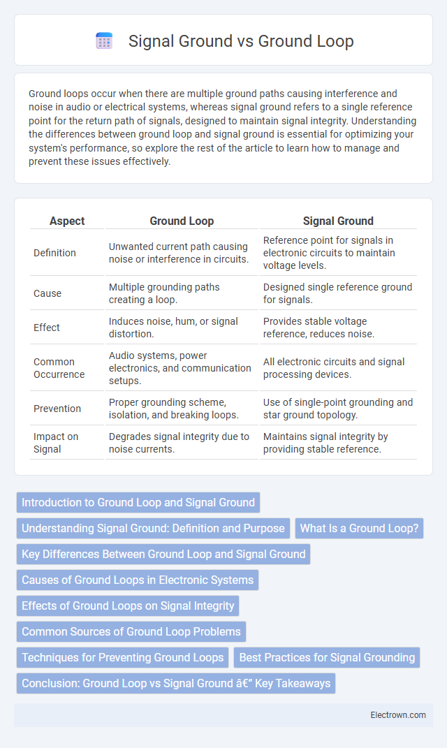
| Aspect | Ground Loop | Signal Ground |
|---|---|---|
| Definition | Unwanted current path causing noise or interference in circuits. | Reference point for signals in electronic circuits to maintain voltage levels. |
| Cause | Multiple grounding paths creating a loop. | Designed single reference ground for signals. |
| Effect | Induces noise, hum, or signal distortion. | Provides stable voltage reference, reduces noise. |
| Common Occurrence | Audio systems, power electronics, and communication setups. | All electronic circuits and signal processing devices. |
| Prevention | Proper grounding scheme, isolation, and breaking loops. | Use of single-point grounding and star ground topology. |
| Impact on Signal | Degrades signal integrity due to noise currents. | Maintains signal integrity by providing stable reference. |
Introduction to Ground Loop and Signal Ground
Ground loops occur when multiple grounding paths create unwanted current flow, causing noise and interference in audio and electronic systems. Signal ground serves as the reference point for circuit voltages, ensuring stable operation and minimizing noise by providing a consistent return path for electrical signals. Proper distinction and management of ground loop and signal ground are essential to maintain signal integrity and reduce electromagnetic interference.
Understanding Signal Ground: Definition and Purpose
Signal ground serves as a common reference point for electronic circuits, ensuring accurate voltage measurements and stable operation by minimizing noise interference. Unlike ground loops, which occur when multiple ground paths create unwanted current flow and noise, signal ground is designed to maintain signal integrity by providing a single, low-impedance return path. Proper implementation of signal ground is crucial for reducing electromagnetic interference and enhancing the performance of sensitive audio, communication, and instrumentation systems.
What Is a Ground Loop?
A ground loop occurs when two or more grounding paths exist in an electrical system, causing unwanted current to flow between them and creating interference or noise in audio, video, or data signals. Signal ground refers to the reference point within a circuit that provides a stable return path for electrical signals, maintaining signal integrity without introducing noise. Understanding the difference between ground loop and signal ground is essential for troubleshooting electrical interference and ensuring your system's optimal performance.
Key Differences Between Ground Loop and Signal Ground
Ground loop occurs when multiple grounding paths create unwanted current flow, causing noise and interference in audio or electrical systems, while signal ground serves as the reference point for circuit signals, ensuring stable voltage levels. Ground loop issues often manifest as hum or buzz in audio equipment, whereas signal ground maintains signal integrity without introducing noise. Unlike signal ground, ground loops result from improper grounding configurations involving multiple devices connected to different ground potentials.
Causes of Ground Loops in Electronic Systems
Ground loops in electronic systems are primarily caused by multiple grounding paths that create unintended current flow between different ground potentials. These loops arise when interconnected devices have grounds at varying voltage levels due to differences in wiring, shielding, or grounding points, leading to interference and noise. Understanding the distinction between ground loop and signal ground helps you identify and mitigate noise sources for improved audio and signal integrity.
Effects of Ground Loops on Signal Integrity
Ground loops create unwanted current paths that induce noise and hum in audio and data signals, significantly degrading signal integrity. These loops generate electromagnetic interference, causing signal distortion and reducing the clarity and accuracy of sensitive measurements. Proper grounding techniques and isolation methods are essential to eliminate ground loop effects and maintain optimal signal performance.
Common Sources of Ground Loop Problems
Common sources of ground loop problems include multiple grounding points connected at different potentials, creating unwanted current paths that induce noise and hum in audio or video systems. Improper shielding, long cable runs, and interconnected equipment with separate power supplies increase the risk of ground loop interference. Identifying and controlling these issues by ensuring a single, consistent signal ground reference can significantly reduce noise and improve system performance.
Techniques for Preventing Ground Loops
Techniques for preventing ground loops include using star grounding, where all grounds connect to a single reference point to minimize potential differences. Employing isolation transformers or optocouplers effectively breaks ground loop currents by electrically isolating signal grounds from power grounds. Proper cable shielding and twisting, along with maintaining short ground return paths, help reduce electromagnetic interference and ground loop noise in sensitive audio or measurement systems.
Best Practices for Signal Grounding
Best practices for signal grounding emphasize isolating the signal ground from the ground loop to prevent noise and interference in sensitive electronic circuits. Using a single-point ground connection or star grounding technique minimizes ground potential differences and reduces the risk of ground loop currents disrupting signal integrity. Ensuring proper shield grounding and implementing differential signaling further enhances noise immunity and overall system performance.
Conclusion: Ground Loop vs Signal Ground – Key Takeaways
Ground loops occur when multiple ground paths create unwanted current flow, causing noise and interference in audio or electronic systems, whereas signal ground refers to the designated reference point for circuit signals that ensures proper device operation. Minimizing ground loops involves careful system design, such as using a single grounding point or isolating grounds, while maintaining a consistent and stable signal ground prevents voltage fluctuations and preserves signal integrity. Understanding the distinction between ground loop and signal ground is essential for optimizing performance and reducing electromagnetic interference in complex electronic setups.
Ground Loop vs Signal Ground Infographic