A frequency divider reduces the input signal's frequency by a specific ratio, enabling easier processing in digital circuits, while a phase divider splits the phase of the input signal into multiple parts without altering the frequency, crucial for applications involving phase-shifted signals. To better understand how each impacts your electronic design, continue reading the full comparison.
Table of Comparison
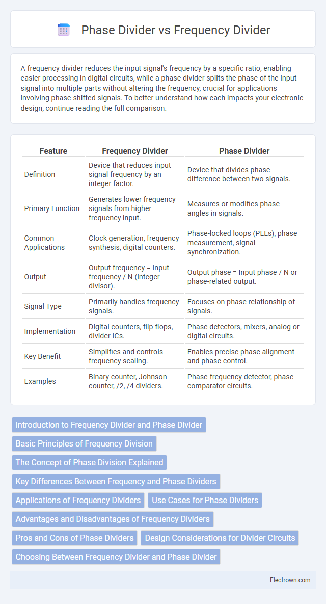
| Feature | Frequency Divider | Phase Divider |
|---|---|---|
| Definition | Device that reduces input signal frequency by an integer factor. | Device that divides phase difference between two signals. |
| Primary Function | Generates lower frequency signals from higher frequency input. | Measures or modifies phase angles in signals. |
| Common Applications | Clock generation, frequency synthesis, digital counters. | Phase-locked loops (PLLs), phase measurement, signal synchronization. |
| Output | Output frequency = Input frequency / N (integer divisor). | Output phase = Input phase / N or phase-related output. |
| Signal Type | Primarily handles frequency signals. | Focuses on phase relationship of signals. |
| Implementation | Digital counters, flip-flops, divider ICs. | Phase detectors, mixers, analog or digital circuits. |
| Key Benefit | Simplifies and controls frequency scaling. | Enables precise phase alignment and phase control. |
| Examples | Binary counter, Johnson counter, /2, /4 dividers. | Phase-frequency detector, phase comparator circuits. |
Introduction to Frequency Divider and Phase Divider
Frequency dividers reduce the frequency of an input signal by a specific integer factor, producing an output signal with a frequency that is a submultiple of the original. Phase dividers, on the other hand, manipulate the phase of an input signal to generate an output phase that is a fraction of the input phase, often used in phase-locked loops (PLLs) for frequency synthesis and timing adjustments. Understanding the fundamental differences between frequency and phase dividers helps optimize your circuit design for applications requiring precise frequency control or phase synchronization.
Basic Principles of Frequency Division
Frequency dividers work by reducing the input signal frequency to a lower, precise fraction, typically using flip-flops or counters operating in digital circuits. Phase dividers adjust the phase of an input signal without altering its frequency, shifting the signal's timing relationship rather than its rate. Your choice between frequency and phase division depends on whether frequency scaling or phase adjustment is required in your application.
The Concept of Phase Division Explained
Phase division involves splitting a signal's phase into multiple equal parts, enabling precise timing and synchronization in communication systems and signal processing. Unlike frequency dividers, which reduce the input signal's frequency, phase dividers focus on generating phase-shifted versions of the original signal without altering its frequency. This concept is essential in applications such as phased array antennas and clock distribution networks, where accurate phase relationships are critical.
Key Differences Between Frequency and Phase Dividers
Frequency dividers reduce the input signal frequency by a specific ratio, producing an output with a lower frequency, while phase dividers focus on shifting the input phase without altering its frequency. Frequency dividers typically use flip-flops or counters to divide the frequency, whereas phase dividers employ phase-locked loops (PLLs) or delay-locked loops (DLLs) to manipulate signal phase. Understanding these key differences helps you select the appropriate component for applications requiring frequency scaling or precise phase control.
Applications of Frequency Dividers
Frequency dividers are essential in digital communication systems, clock generation, and signal processing, where they reduce the frequency of input signals to synchronize circuits or generate stable timing references. Unlike phase dividers that primarily adjust signal phase without altering frequency, frequency dividers create harmonics for use in synthesizers, frequency modulation, and data transmission protocols. Your circuit design benefits from frequency dividers when precise frequency scaling or timing control is required across telecommunications, microprocessors, and RF applications.
Use Cases for Phase Dividers
Phase dividers are primarily used in communication systems for phase-locked loops (PLLs), where precise phase comparison and synchronization are critical. They enable accurate phase alignment in applications like frequency synthesis, signal demodulation, and clock recovery circuits. Unlike frequency dividers that focus on reducing signal frequency, phase dividers specialize in preserving and manipulating phase information for timing and control purposes.
Advantages and Disadvantages of Frequency Dividers
Frequency dividers reduce the input signal frequency to a lower output frequency, enabling easier signal processing in digital circuits, clock generation, and communication systems. Their advantages include simplicity, low power consumption, and reliable operation at high frequencies, but they may introduce phase noise and limit frequency resolution compared to phase dividers. Understanding these trade-offs helps you select the appropriate divider for your specific timing and frequency synthesis applications.
Pros and Cons of Phase Dividers
Phase dividers effectively split an input signal's phase into multiple outputs, providing precise phase relationships critical for applications like signal processing and communication systems. Their advantage lies in maintaining signal integrity and low jitter, but they often require complex circuitry and consume more power compared to frequency dividers. Your choice depends on the need for phase accuracy versus simplicity and power efficiency in the design.
Design Considerations for Divider Circuits
Design considerations for frequency divider circuits emphasize stable oscillation and accurate signal scaling, requiring low phase noise and minimal jitter to maintain signal integrity. Phase divider design focuses on precise phase shift control and synchronization, often implementing feedback loops to reduce phase error and improve timing accuracy. Your choice between frequency and phase dividers should align with the application's demand for either frequency division or phase alignment to optimize overall circuit performance.
Choosing Between Frequency Divider and Phase Divider
Choosing between a frequency divider and a phase divider depends on the specific application requirements such as signal processing and synchronization. Frequency dividers reduce the input signal frequency by an integer factor, making them ideal for clock generation and frequency synthesis in digital circuits. Phase dividers, on the other hand, maintain the input frequency while adjusting the phase relationship, which is critical for phase-locked loops (PLLs) and timing alignment in communication systems.
Frequency Divider vs Phase Divider Infographic