A series circuit has components connected end-to-end, so the current flows through each component sequentially, causing voltage to drop across each device; a parallel circuit has components connected across the same voltage source, allowing current to split and flow through multiple paths simultaneously. Understanding these differences can help you optimize your electrical designs--read on to explore their unique advantages and applications.
Table of Comparison
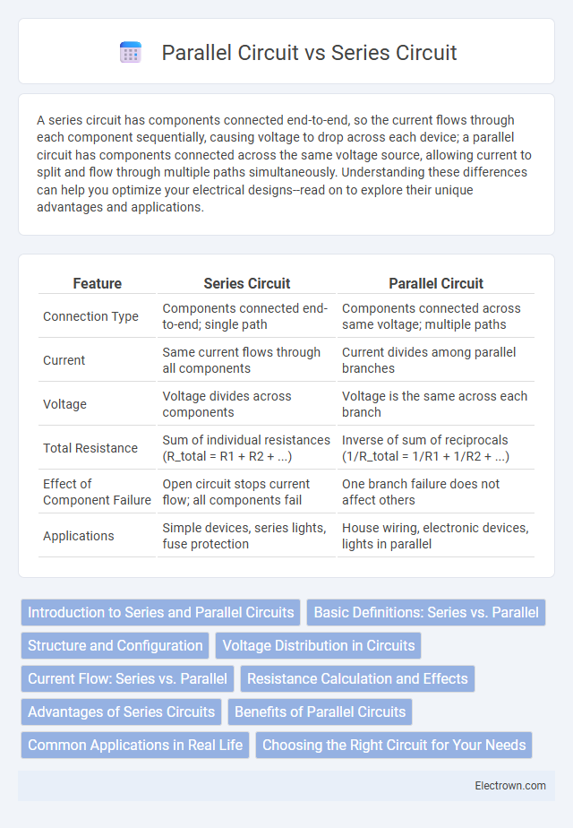
| Feature | Series Circuit | Parallel Circuit |
|---|---|---|
| Connection Type | Components connected end-to-end; single path | Components connected across same voltage; multiple paths |
| Current | Same current flows through all components | Current divides among parallel branches |
| Voltage | Voltage divides across components | Voltage is the same across each branch |
| Total Resistance | Sum of individual resistances (R_total = R1 + R2 + ...) | Inverse of sum of reciprocals (1/R_total = 1/R1 + 1/R2 + ...) |
| Effect of Component Failure | Open circuit stops current flow; all components fail | One branch failure does not affect others |
| Applications | Simple devices, series lights, fuse protection | House wiring, electronic devices, lights in parallel |
Introduction to Series and Parallel Circuits
Series circuits connect components end-to-end, allowing current to flow through a single path, making voltage drop additive across each element. Parallel circuits feature multiple paths for current, ensuring the voltage across each component remains the same while total current divides according to resistance. Understanding the distinct behavior of current and voltage in series versus parallel configurations is essential for circuit design and analysis in electronics.
Basic Definitions: Series vs. Parallel
A series circuit consists of components connected end-to-end, forming a single path for electric current, while a parallel circuit features components connected across common points, creating multiple current paths. In series circuits, current remains constant through all components whereas voltage divides among them; in parallel circuits, voltage across each component is equal, but current splits according to each branch's resistance. The fundamental difference lies in how voltage, current, and resistance behave, impacting circuit design and functionality in electrical systems.
Structure and Configuration
A series circuit features components connected end-to-end, forming a single path for current flow, causing the same current to pass through all elements. In contrast, a parallel circuit arranges components across multiple branches, each providing an independent path for current, so voltage remains consistent across all elements. Understanding your circuit's structure helps determine performance, with series circuits favoring uniform current and parallel circuits ensuring stable voltage distribution.
Voltage Distribution in Circuits
In a series circuit, voltage divides proportionally across components based on their resistance, causing the total voltage to equal the sum of individual voltage drops. Conversely, in a parallel circuit, each branch experiences the full source voltage, ensuring identical voltage across all components regardless of resistance. This fundamental difference in voltage distribution significantly impacts circuit design and functionality in electronic systems.
Current Flow: Series vs. Parallel
In a series circuit, the current flow is the same through all components because there is only one path for electrons to travel, making the total current constant. In contrast, a parallel circuit allows current to split across multiple branches, so the total current is the sum of the currents in each branch, enabling independent operation of components. Understanding the difference in current flow between series and parallel circuits can help you design efficient electrical systems tailored to your needs.
Resistance Calculation and Effects
In a series circuit, total resistance is the sum of all individual resistances, increasing overall resistance and reducing current flow. In contrast, a parallel circuit's total resistance decreases as additional branches are added, calculated using the reciprocal formula 1/R_total = 1/R1 + 1/R2 + ..., which allows higher current flow. Your choice between series and parallel configurations directly affects the resistance behavior and efficiency of your electrical system.
Advantages of Series Circuits
Series circuits offer the advantage of simplicity in design, making them easier and cheaper to construct and troubleshoot. They ensure a uniform current flow through all components, which is beneficial for devices requiring consistent current levels. Their low wiring requirements reduce space utilization and minimize potential points of failure in small-scale electrical applications.
Benefits of Parallel Circuits
Parallel circuits provide consistent voltage across all components, ensuring devices operate efficiently and uniformly. They allow independent control of each device, so one component can be turned off without affecting the entire circuit. Enhanced reliability and easier troubleshooting make parallel circuits ideal for household wiring and complex electronic systems.
Common Applications in Real Life
Series circuits are commonly used in applications like Christmas lights and old-style flashlights, where the same current flows through all components, ensuring synchronized operation but causing the entire circuit to fail if one component breaks. Parallel circuits are prevalent in household electrical wiring and automotive lighting systems, providing independent paths for current flow so that devices operate independently without interruption. The choice between series and parallel circuits depends on the need for uniform current flow versus reliable, independent component operation in practical electrical and electronic systems.
Choosing the Right Circuit for Your Needs
Selecting between series and parallel circuits depends on the desired electrical performance and application. Series circuits are ideal for applications requiring uniform current flow and simple wiring, though a single component failure interrupts the entire circuit. Parallel circuits offer independent paths for components, ensuring consistent voltage and reliability, making them suitable for complex devices where uninterrupted operation is critical.
Series circuit vs parallel circuit Infographic