Ground planes serve as a reference point for voltage levels and help reduce electromagnetic interference and noise in electronic circuits, while power planes distribute electrical power evenly across the PCB to ensure stable voltage supply. Understanding the differences between ground planes and power planes is essential for optimizing your circuit design; read on to explore their roles and benefits in detail.
Table of Comparison
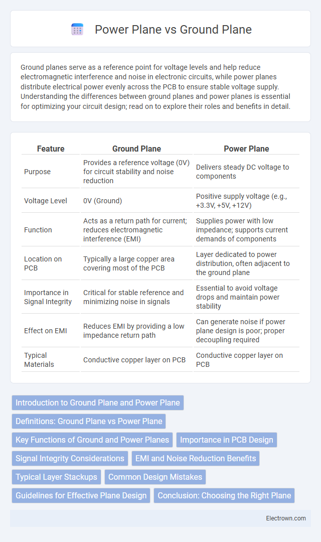
| Feature | Ground Plane | Power Plane |
|---|---|---|
| Purpose | Provides a reference voltage (0V) for circuit stability and noise reduction | Delivers steady DC voltage to components |
| Voltage Level | 0V (Ground) | Positive supply voltage (e.g., +3.3V, +5V, +12V) |
| Function | Acts as a return path for current; reduces electromagnetic interference (EMI) | Supplies power with low impedance; supports current demands of components |
| Location on PCB | Typically a large copper area covering most of the PCB | Layer dedicated to power distribution, often adjacent to the ground plane |
| Importance in Signal Integrity | Critical for stable reference and minimizing noise in signals | Essential to avoid voltage drops and maintain power stability |
| Effect on EMI | Reduces EMI by providing a low impedance return path | Can generate noise if power plane design is poor; proper decoupling required |
| Typical Materials | Conductive copper layer on PCB | Conductive copper layer on PCB |
Introduction to Ground Plane and Power Plane
A ground plane is a continuous conductive layer serving as a reference point for electrical circuits, minimizing noise and interference by providing a stable return path for current. A power plane distributes supply voltage uniformly across the PCB, ensuring stable and consistent power delivery to components. Both planes are critical for maintaining signal integrity and reducing electromagnetic interference in high-speed electronic designs.
Definitions: Ground Plane vs Power Plane
A ground plane is a large conductive surface, usually a copper layer on a PCB, intended to serve as a common return path for electrical current and to minimize electromagnetic interference (EMI). A power plane is a dedicated conductive layer that distributes power supply voltage uniformly across the PCB to various components. Both planes are crucial in PCB design for signal integrity, with the ground plane ensuring a stable reference voltage and the power plane maintaining consistent power delivery.
Key Functions of Ground and Power Planes
Ground planes provide a stable reference voltage and help minimize electromagnetic interference (EMI) by offering a low-impedance return path for current in your circuit. Power planes deliver consistent voltage levels to components, ensuring efficient power distribution and reducing voltage drops across the printed circuit board (PCB). Both planes play critical roles in maintaining signal integrity and overall electrical performance in high-frequency designs.
Importance in PCB Design
Ground planes and power planes are crucial for minimizing electromagnetic interference and enhancing signal integrity in PCB design. A dedicated ground plane provides a low-impedance return path for signals, reducing noise and maintaining stable voltage references. Power planes ensure efficient distribution of electrical power, improving voltage regulation and reducing voltage drops across the board.
Signal Integrity Considerations
Ground planes provide a stable reference voltage, minimizing noise and improving signal return path continuity, which is critical for maintaining signal integrity. Power planes must be carefully managed to prevent voltage fluctuations and minimize electromagnetic interference that can degrade signal quality. Your PCB design benefits from maintaining low impedance and consistent reference planes to ensure optimal signal integrity in high-speed circuits.
EMI and Noise Reduction Benefits
Ground planes provide a low-impedance path that significantly reduces electromagnetic interference (EMI) by minimizing loop areas and improving signal return paths. Power planes contribute to noise reduction by offering stable voltage levels and reducing power supply fluctuations, which helps maintain signal integrity. Optimizing the layout of both ground and power planes improves overall electromagnetic compatibility (EMC), enhancing your circuit's performance in noisy environments.
Typical Layer Stackups
Typical layer stackups in printed circuit boards (PCBs) often include distinct ground and power planes strategically placed within the board's internal layers to minimize electromagnetic interference and enhance signal integrity. A common configuration consists of an outer signal layer, followed by an adjacent ground plane layer, then a power plane layer, and another signal layer, which forms a four-layer stackup providing low impedance reference planes for high-speed signals. Advanced multilayer PCBs may use interleaved ground and power planes to create controlled impedance environments and improve noise isolation in complex high-frequency designs.
Common Design Mistakes
Common design mistakes in Ground Plane vs Power Plane implementation include improper segmentation of ground planes, which leads to increased electromagnetic interference (EMI) and signal integrity issues. Overlapping or insufficiently isolated power and ground planes can cause noise coupling and voltage drops, reducing overall circuit stability. Failing to maintain continuous ground planes beneath signal layers disrupts return current paths, resulting in signal distortion and degraded high-frequency performance.
Guidelines for Effective Plane Design
Effective plane design requires separating ground planes and power planes to reduce noise coupling and maintain signal integrity. You should ensure low impedance paths by keeping planes continuous and minimizing splits or gaps under critical components. Proper stacking order and decoupling capacitor placement are essential for optimizing signal return paths and power distribution.
Conclusion: Choosing the Right Plane
Selecting the right plane between ground and power is crucial for ensuring signal integrity and minimizing electromagnetic interference in your PCB design. Ground planes provide a low-impedance return path and help reduce noise, while power planes deliver stable voltage distribution across components. Your choice depends on the design requirements, with optimized use of both planes yielding the best electrical performance and reliability.
Ground Plane vs Power Plane Infographic