PCB trace offers a compact, reliable, and precise method for electrical connections on circuit boards, ensuring minimal signal interference and enhanced durability compared to traditional wire connections. Explore the rest of the article to understand how choosing the right connection method can impact your electronic project's performance.
Table of Comparison
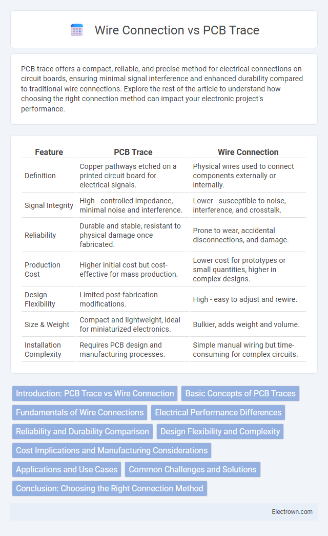
| Feature | PCB Trace | Wire Connection |
|---|---|---|
| Definition | Copper pathways etched on a printed circuit board for electrical signals. | Physical wires used to connect components externally or internally. |
| Signal Integrity | High - controlled impedance, minimal noise and interference. | Lower - susceptible to noise, interference, and crosstalk. |
| Reliability | Durable and stable, resistant to physical damage once fabricated. | Prone to wear, accidental disconnections, and damage. |
| Production Cost | Higher initial cost but cost-effective for mass production. | Lower cost for prototypes or small quantities, higher in complex designs. |
| Design Flexibility | Limited post-fabrication modifications. | High - easy to adjust and rewire. |
| Size & Weight | Compact and lightweight, ideal for miniaturized electronics. | Bulkier, adds weight and volume. |
| Installation Complexity | Requires PCB design and manufacturing processes. | Simple manual wiring but time-consuming for complex circuits. |
Introduction: PCB Trace vs Wire Connection
PCB traces, composed of thin copper paths etched onto a printed circuit board, offer precise, reliable, and compact electrical connections ideal for high-frequency and complex circuits. Wire connections, typically insulated copper wires, provide flexibility and easy modification but can introduce noise and take up more space. Optimizing signal integrity and minimizing interference often favor PCB traces in modern electronic designs.
Basic Concepts of PCB Traces
PCB traces are thin copper pathways etched onto a circuit board that electrically connect components by carrying signals and power. Their width, thickness, and length directly influence the current capacity and signal integrity, making proper design essential to avoid overheating or signal loss. Your understanding of trace impedance, resistance, and inductance is crucial for optimizing performance and ensuring reliable electronic connections compared to traditional wire connections.
Fundamentals of Wire Connections
Wire connections rely on physical linking of conductive materials to transmit electrical signals, ensuring flexibility in layout and repair. They consist of insulated conductors joined by soldering, crimping, or terminal blocks, providing customizable lengths and easy modifications. Understanding the fundamentals of wire gauge, insulation type, and connection integrity is essential for reliable circuit performance and safety in your projects.
Electrical Performance Differences
PCB traces offer lower inductance and consistent impedance compared to wire connections, resulting in improved high-frequency signal integrity and reduced electromagnetic interference (EMI). The controlled geometry of PCB traces minimizes signal delay and crosstalk, enhancing overall electrical performance in complex circuits. In contrast, wire connections exhibit higher parasitic inductance and variability, which can degrade signal quality and limit performance in high-speed applications.
Reliability and Durability Comparison
PCB trace connections offer superior reliability due to their fixed, controlled pathways and uniform material properties, minimizing signal loss and interference compared to wire connections. Wire connections are more susceptible to mechanical stress, corrosion, and oxidation, which can degrade performance and reduce durability over time. The integrated nature of PCB traces enhances durability by preventing physical displacement and ensuring consistent electrical conductivity under varying environmental conditions.
Design Flexibility and Complexity
PCB trace design offers greater flexibility in creating compact and intricate circuit layouts with precise control over signal paths, enabling high-density component integration. Wire connections add complexity due to physical routing constraints, potential signal interference, and manual assembly challenges that can affect reliability. You can achieve more streamlined and automated manufacturing processes with PCB traces, making them ideal for advanced electronic designs requiring consistent performance.
Cost Implications and Manufacturing Considerations
PCB traces offer lower production costs compared to wire connections due to automated fabrication processes and reduced material usage. Wire connections increase labor hours and material expenses, often requiring manual soldering and additional insulation components. Your choice impacts overall manufacturing efficiency, with PCB traces favoring high-volume production scalability.
Applications and Use Cases
PCB traces are preferred in high-frequency and compact electronic devices where precise signal integrity and controlled impedance are crucial, such as in smartphones, computers, and aerospace systems. Wire connections find extensive use in prototyping, repair, and high-power applications like automotive wiring harnesses and industrial machinery due to their flexibility and ease of modification. Each method suits different scenarios based on factors like durability, signal requirements, and environmental conditions.
Common Challenges and Solutions
PCB trace connections often face challenges such as signal interference and impedance mismatches, which can degrade circuit performance. Wire connections, while flexible, may introduce inductance and resistance issues that affect signal integrity and increase noise susceptibility. To optimize Your design, using proper trace width calculations and high-quality shielding for wires can effectively mitigate these common problems.
Conclusion: Choosing the Right Connection Method
Selecting the appropriate connection method between PCB trace and wire connection depends on factors like current capacity, signal integrity, and space constraints. PCB traces offer high reliability and compact design ideal for low to moderate current applications, while wire connections provide flexibility and ease of modification for higher power or complex routing needs. Your decision should align with the electrical and mechanical requirements of your project to ensure optimal performance and durability.
PCB Trace vs Wire Connection Infographic