Voltage mode logic (VML) uses voltage levels to represent binary states, offering simplicity and ease of interfacing with digital circuits, while current mode logic (CML) relies on current steering for faster switching speeds and lower voltage swings, resulting in better performance for high-frequency applications. Explore this article to understand the advantages and trade-offs of each logic type to optimize Your digital circuit design.
Table of Comparison
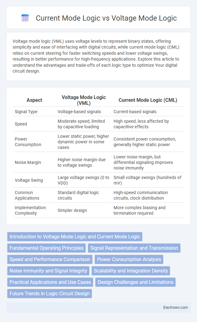
| Aspect | Voltage Mode Logic (VML) | Current Mode Logic (CML) |
|---|---|---|
| Signal Type | Voltage-based signals | Current-based signals |
| Speed | Moderate speed, limited by capacitive loading | High speed, less affected by capacitive effects |
| Power Consumption | Lower static power, higher dynamic power in some cases | Consistent power consumption, generally higher static power |
| Noise Margin | Higher noise margin due to voltage swings | Lower noise margin, but differential signaling improves noise immunity |
| Voltage Swing | Large voltage swings (0 to VDD) | Small voltage swings (hundreds of mV) |
| Common Applications | Standard digital logic circuits | High-speed communication circuits, clock distribution |
| Implementation Complexity | Simpler design | More complex biasing and termination required |
Introduction to Voltage Mode Logic and Current Mode Logic
Voltage Mode Logic (VML) operates by representing binary states through voltage levels, making it the traditional approach in digital circuits with high noise immunity and well-established design methodologies. Current Mode Logic (CML) differentiates itself by encoding information using current levels, offering faster switching speeds and lower voltage swings, which reduces power consumption and improves signal integrity in high-frequency applications. Understanding the distinct operational principles of VML and CML aids in selecting the appropriate logic family based on speed, power efficiency, and noise tolerance requirements.
Fundamental Operating Principles
Voltage Mode Logic (VML) operates by using voltage levels to represent binary states, where digital signals are interpreted based on distinct voltage thresholds. Current Mode Logic (CML) differentiates itself by encoding data through variations in current flow rather than voltage, enabling faster switching speeds and reduced voltage swing noise. The fundamental operating principle of VML centers on voltage amplitude control, while CML relies on controlled current steering, making CML more suitable for high-speed, low-noise applications.
Signal Representation and Transmission
Voltage mode logic (VML) represents signals through voltage levels, relying on voltage swings between defined high and low states for transmission, which often results in greater power consumption and susceptibility to noise. Current mode logic (CML) encodes signals as current variations, enabling faster switching speeds, improved noise immunity, and reduced voltage swings that contribute to lower power dissipation. Transmission in CML benefits from constant current flow and differential signaling, which enhances signal integrity and reduces electromagnetic interference compared to the single-ended voltage-driven signals in VML.
Speed and Performance Comparison
Voltage Mode Logic (VML) generally offers slower switching speeds due to its reliance on voltage levels to represent data, which results in higher capacitive loading and slower signal transitions. Current Mode Logic (CML) achieves higher speed and better performance by operating with constant current sources, minimizing voltage swing and reducing switching times, making it ideal for high-frequency applications such as RF circuits and high-speed communication systems. The intrinsic design of CML enables greater bandwidth and lower propagation delay compared to VML, directly enhancing overall circuit speed and performance.
Power Consumption Analysis
Voltage mode logic (VML) typically consumes more power due to continuous charging and discharging of load capacitances, resulting in significant dynamic power dissipation. Current mode logic (CML) offers lower power consumption by operating with constant current biasing, minimizing voltage swings and reducing switching losses. The power efficiency of CML makes it preferable in high-speed and low-power integrated circuit applications.
Noise Immunity and Signal Integrity
Voltage Mode Logic (VML) typically exhibits higher noise immunity due to its larger voltage swing, which ensures clearer distinction between logic levels and reduces susceptibility to electromagnetic interference. Current Mode Logic (CML) benefits from superior signal integrity at high frequencies because of its constant current operation, minimizing voltage fluctuations and crosstalk on transmission lines. The choice between VML and CML critically impacts system performance in high-speed digital circuits where noise resilience and signal clarity drive reliability.
Scalability and Integration Density
Voltage mode logic (VML) offers higher integration density due to its compatibility with standard CMOS technology, enabling more compact circuit layouts and easier scaling for complex designs. Current mode logic (CML) provides faster switching speeds but typically requires more complex biasing and larger device sizes, which can limit scalability in highly integrated systems. Choosing between VML and CML depends on Your specific needs for balancing speed and integration density in scalable semiconductor architectures.
Practical Applications and Use Cases
Voltage mode logic (VML) is commonly used in digital integrated circuits such as microprocessors and memory devices due to its straightforward design and compatibility with CMOS technology. Current mode logic (CML) excels in high-speed communication systems, including high-frequency data converters and RF circuits, because of its fast switching speeds and low voltage swings. VML suits low-power applications in battery-operated devices, while CML is preferred for ultra-fast data transmission in optical and wired communications.
Design Challenges and Limitations
Voltage Mode Logic (VML) faces design challenges such as limited speed and high power consumption due to voltage swing requirements and capacitive loading, which can hinder performance in high-frequency applications. Current Mode Logic (CML) overcomes some speed limitations by maintaining constant current flow, but it introduces complexities like increased circuit complexity and power dissipation, posing limitations for low-power designs. Your choice between VML and CML must consider trade-offs in noise susceptibility, power efficiency, and integration complexity based on application requirements.
Future Trends in Logic Circuit Design
Future trends in logic circuit design emphasize the growing importance of Current Mode Logic (CML) due to its superior speed and reduced voltage swings, which enhance performance in high-frequency applications. Voltage Mode Logic (VML) continues to evolve with advancements in low-power and scalable CMOS technologies, aiming to balance power efficiency with integration density. Emerging hybrid architectures integrating both VML and CML principles are being researched to optimize power consumption, signal integrity, and operational speed for next-generation communication and computing systems.
Voltage mode logic vs current mode logic Infographic