Pass gates and transmission gates both serve as essential switches in CMOS technology, with pass gates typically using a single transistor type, resulting in incomplete voltage transfer, while transmission gates combine both NMOS and PMOS transistors to provide better voltage-level restoration and lower resistance. Understanding the key differences in their operation and performance can help you optimize your circuit designs; continue reading to explore their applications and advantages in detail.
Table of Comparison
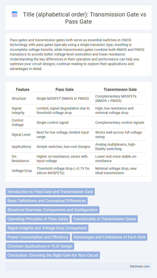
| Feature | Pass Gate | Transmission Gate |
|---|---|---|
| Structure | Single MOSFET (NMOS or PMOS) | Complementary MOSFETs (NMOS + PMOS) |
| Signal Integrity | Limited, signal degradation due to threshold voltage drop | High, low resistance and minimal voltage drop |
| Control Voltage | Single control signal | Complementary control signals |
| Signal Level | Best for low voltage, limited input range | Works well across full voltage swing |
| Applications | Simple switches, low-cost designs | Analog multiplexers, high-fidelity switching |
| On-Resistance | Higher on-resistance, varies with input voltage | Lower and more stable on-resistance |
| Voltage Drop | Threshold voltage drop (~0.7V for silicon MOSFETs) | Minimal voltage drop, near ideal transmission |
Introduction to Pass Gate and Transmission Gate
Pass gates and transmission gates are fundamental components in digital circuits used to control signal flow by acting as switches. A pass gate typically uses a single transistor, either NMOS or PMOS, to pass signals, but it suffers from threshold voltage drops and limited voltage swing. Transmission gates combine both NMOS and PMOS transistors in parallel, providing better voltage transfer characteristics and improved signal integrity, making them ideal for analog multiplexers and bidirectional switches in your designs.
Basic Definitions and Conceptual Differences
A Pass Gate is a single MOSFET transistor used to control signal flow by either passing or blocking the input voltage, functioning as a simple switch. A Transmission Gate integrates both NMOS and PMOS transistors in parallel, enabling bidirectional signal transmission with lower resistance and better voltage swing across a wider range. You should choose a transmission gate when improved signal integrity and full voltage transmission are critical in your digital circuit design.
Structural Overview: Components and Configuration
A Pass Gate typically consists of a single NMOS or PMOS transistor used for signal transmission, limiting its effectiveness in passing a full voltage range due to threshold voltage drop. A Transmission Gate integrates both NMOS and PMOS transistors connected in parallel, allowing bidirectional signal flow and minimizing voltage drop by compensating each other's weaknesses. The complementary arrangement in a Transmission Gate enhances overall conductivity and signal integrity compared to the single-transistor Pass Gate structure.
Operating Principles of Pass Gates
Pass gates operate by controlling the conduction of a single type of MOS transistor, either NMOS or PMOS, which allows signals to pass when the gate voltage is active, but can cause signal degradation due to threshold voltage drops. Transmission gates combine both NMOS and PMOS transistors in parallel, enabling bidirectional signal flow with reduced voltage loss and better signal integrity by effectively passing both high and low logic levels. The operating principle of pass gates centers on utilizing transistor conduction controlled by gate voltage, while transmission gates leverage complementary transistor pairs to enhance switching performance and reduce on-resistance.
Functionality of Transmission Gates
Transmission gates function as bidirectional switches that allow signals to pass through when enabled, providing low resistance paths for both high and low logic levels. Unlike single pass gates which use only one type of transistor, transmission gates combine complementary MOSFETs (both NMOS and PMOS) to minimize voltage threshold drop and achieve near-ideal signal transmission. This complementary configuration ensures efficient signal propagation in analog and digital circuits, making transmission gates essential for applications like multiplexers, switches, and sample-and-hold circuits.
Signal Integrity and Voltage Drop Comparison
Pass gates and transmission gates both serve as electronic switches in CMOS circuits, but transmission gates offer superior signal integrity due to their complementary MOSFET structure, which minimizes voltage drop and reduces signal distortion. In pass gates that use a single type of transistor, voltage drop occurs because the transistor cannot pass both high and low logic levels effectively, leading to degraded signal levels and potential logic errors. Transmission gates, by combining NMOS and PMOS transistors, ensure near full rail-to-rail output voltage, maintaining stronger signal integrity and minimizing voltage drop across a wider range of input signals.
Power Consumption and Efficiency
Pass gates typically consume less power than transmission gates because they use a single type of transistor, reducing leakage current and overall capacitance. Transmission gates, combining both NMOS and PMOS transistors, offer better signal integrity and switching efficiency but can result in slightly higher power consumption due to increased transistor count. Your choice depends on balancing the need for power efficiency and signal quality in your specific circuit design.
Advantages and Limitations of Each Gate
Pass gates offer simpler design and lower power consumption, making them ideal for analog signal transmission and multiplexers, but they suffer from threshold voltage drops that limit their voltage range. Transmission gates overcome this limitation by using complementary MOSFETs to provide full voltage swing and better signal integrity, though they require more area and more complex control logic. Your choice between pass gate and transmission gate depends on balancing power efficiency, area constraints, and signal fidelity requirements.
Common Applications in VLSI Design
Pass gates are widely used in multiplexers, data selectors, and clock gating circuits, benefiting from their ability to efficiently control signal flow in VLSI designs. Transmission gates find common applications in analog switch design, level shifters, and sample-and-hold circuits due to their superior bidirectional conduction and reduced voltage drop characteristics. Both gate types enable optimized power consumption and signal integrity, critical in low-power and high-speed integrated circuits.
Conclusion: Choosing the Right Gate for Your Circuit
Pass gates offer faster switching speeds and lower power consumption, making them ideal for high-speed analog multiplexers and simple digital logic. Transmission gates provide superior signal integrity and bidirectional conduction with minimal voltage drop, suitable for precision analog circuits and complex logic paths. Selecting between pass gate and transmission gate depends on prioritizing speed and simplicity versus signal quality and versatility in your circuit design.
Pass Gate vs Transmission Gate Infographic