A clock divider and frequency divider both reduce the frequency of a signal, but a clock divider specifically targets clock signals used in digital circuits to synchronize operations, while a frequency divider can apply to any periodic waveform. Understanding the distinction can optimize your digital design project; explore the article to learn how each affects circuit performance.
Table of Comparison
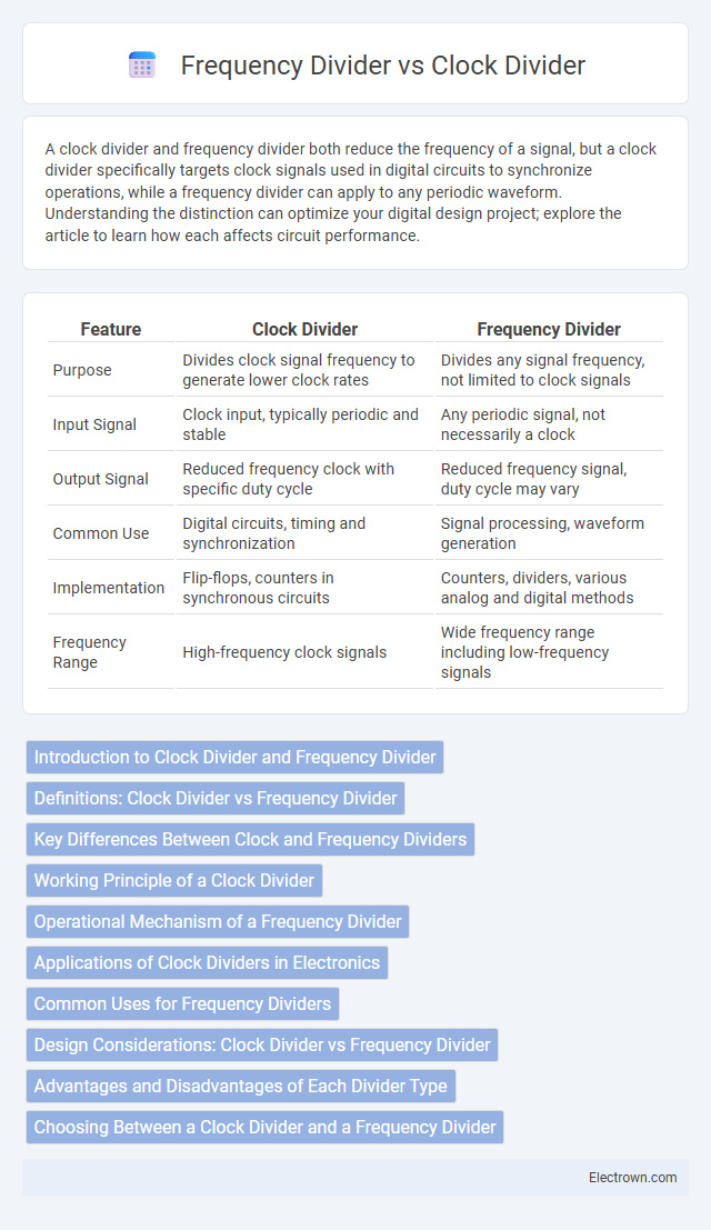
| Feature | Clock Divider | Frequency Divider |
|---|---|---|
| Purpose | Divides clock signal frequency to generate lower clock rates | Divides any signal frequency, not limited to clock signals |
| Input Signal | Clock input, typically periodic and stable | Any periodic signal, not necessarily a clock |
| Output Signal | Reduced frequency clock with specific duty cycle | Reduced frequency signal, duty cycle may vary |
| Common Use | Digital circuits, timing and synchronization | Signal processing, waveform generation |
| Implementation | Flip-flops, counters in synchronous circuits | Counters, dividers, various analog and digital methods |
| Frequency Range | High-frequency clock signals | Wide frequency range including low-frequency signals |
Introduction to Clock Divider and Frequency Divider
A clock divider is an electronic circuit that reduces the frequency of an input clock signal by a specific ratio, generating a lower-frequency clock output used for synchronization in digital systems. A frequency divider performs a similar role by generating an output signal whose frequency is a fraction of the input signal frequency, often implemented using flip-flops or counters to achieve precise frequency scaling. Both clock dividers and frequency dividers are essential in applications like microprocessors, communication systems, and timing circuits where controlled timing and frequency adjustments are critical.
Definitions: Clock Divider vs Frequency Divider
A Clock Divider is a circuit that reduces the frequency of a clock signal by producing an output with a lower frequency derived from the input clock, often used to synchronize signals in digital systems. A Frequency Divider splits the input frequency into a fraction or multiple, generating a new frequency that is a division of the original, commonly utilized in communication and signal processing. Your choice between a clock divider and a frequency divider depends on whether the application requires precise timing synchronization or general frequency scaling.
Key Differences Between Clock and Frequency Dividers
Clock dividers specifically reduce the frequency of a clock signal while maintaining a 50% duty cycle, ensuring synchronization in digital circuits. Frequency dividers generalize this function by dividing any periodic signal frequency, often without preserving the original signal's waveform or duty cycle. The key difference lies in the clock divider's design for precise timing and stability in clock generation versus the frequency divider's broader application in signal processing.
Working Principle of a Clock Divider
A clock divider operates by taking an input clock signal and generating an output clock signal with a reduced frequency, typically achieved through digital counters or flip-flops that divide the input frequency by an integer factor. The working principle relies on counting a predetermined number of input clock pulses before toggling the output, effectively producing a new clock signal at a fraction of the original frequency. This mechanism is essential in synchronous digital circuits for timing adjustments, enabling lower-frequency timing signals derived from a high-frequency clock source.
Operational Mechanism of a Frequency Divider
A frequency divider operates by reducing the frequency of an input signal by an integer factor using digital counters or flip-flops. It segments the input clock pulses into equal intervals, outputting a pulse for every N input pulses, effectively dividing the frequency by N. This mechanism ensures precise timing control in applications like clocks, communication systems, and digital circuits.
Applications of Clock Dividers in Electronics
Clock dividers are essential in electronics for synchronizing digital circuits by reducing high-frequency clock signals to lower, more manageable frequencies. They enable precise timing control in microprocessors, communication systems, and digital signal processors, improving overall system stability and power efficiency. Common applications include generating timing signals for data converters, driving multiplexers, and creating low-frequency clocks for embedded systems.
Common Uses for Frequency Dividers
Frequency dividers are commonly used in digital electronics for generating lower frequency signals from a high-frequency clock source, enabling timing synchronization in microprocessors and communication systems. They are essential in phase-locked loops (PLLs) for frequency synthesis and clock recovery by reducing signal frequency to stable, manageable levels. Frequency dividers also facilitate data rate matching in serial communication interfaces and aid in signal processing for precise measurement and control applications.
Design Considerations: Clock Divider vs Frequency Divider
Design considerations for clock dividers focus on maintaining signal integrity and timing accuracy, ensuring minimal jitter and phase noise to preserve the original clock's characteristics. Frequency dividers emphasize stability and precision in output frequency with low distortion, often designed to handle various division ratios and support synchronization with system clocks. Both types require careful selection of divider architectures, such as flip-flop-based or phase-locked loop (PLL)-based designs, tailored to application-specific requirements like power consumption, complexity, and integration level.
Advantages and Disadvantages of Each Divider Type
Clock dividers offer precise timing control and low jitter, making them ideal for synchronous digital circuits, but they often require complex design and higher power consumption. Frequency dividers are simpler and more power-efficient, suitable for basic frequency scaling, yet they may introduce phase noise and lack the fine synchronization capabilities of clock dividers. Your choice depends on whether you prioritize accuracy and stability (clock divider) or simplicity and efficiency (frequency divider).
Choosing Between a Clock Divider and a Frequency Divider
Choosing between a clock divider and a frequency divider depends on the specific application requirements and signal characteristics. A clock divider typically works with digital clock signals to reduce frequency by integer factors, maintaining synchronization in timing circuits, while a frequency divider can handle a broader range of signal types, including analog and digital, offering more flexibility. Your choice should consider factors such as signal type, desired frequency reduction precision, and the impact on system timing performance.
Clock Divider vs Frequency Divider Infographic