Pre-charge circuits protect your power supply by limiting inrush current during startup, while soft start circuits gradually ramp up voltage to prevent sudden surges and extend component lifespan. Explore the rest of the article to understand which solution best fits your electrical system needs.
Table of Comparison
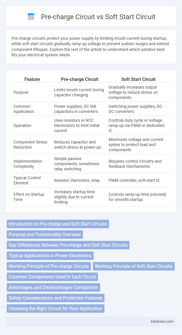
| Feature | Pre-charge Circuit | Soft Start Circuit |
|---|---|---|
| Purpose | Limits inrush current during capacitor charging | Gradually increases output voltage to reduce stress on components |
| Common Application | Power supplies, DC link capacitors in converters | Switching power supplies, DC-DC converters |
| Operation | Uses resistors or NTC thermistors to limit initial current | Controls duty cycle or voltage ramp-up via PWM or dedicated IC |
| Component Stress Reduction | Reduces capacitor and switch stress at power-up | Minimizes voltage and current spikes to protect load and components |
| Implementation Complexity | Simple passive components, sometimes relay switching | Requires control circuitry and feedback mechanisms |
| Typical Control Element | Resistor, thermistor, relay | PWM controller, soft-start IC |
| Effect on Startup Time | Increases startup time slightly due to current limiting | Controls ramp-up time precisely for smooth startup |
Introduction to Pre-charge and Soft Start Circuits
Pre-charge circuits limit inrush current during initial power application by gradually charging the load, protecting components from damage and improving system reliability. Soft start circuits manage voltage ramp-up in power converters or amplifiers, ensuring a smooth increase in output voltage to prevent sudden stress on devices. Both circuits optimize power management and extend electronic device lifespan by controlling initial current and voltage surges.
Purpose and Functionality Overview
Pre-charge circuits limit inrush current by gradually charging the input capacitors to prevent damage to power components, enhancing system reliability in power supply applications. Soft start circuits control the voltage ramp-up during device startup, reducing stress on components by preventing sudden surges in current and voltage. Both circuits are essential for extending the lifespan of electronic devices by managing power transitions smoothly and protecting sensitive circuitry.
Key Differences Between Pre-charge and Soft Start Circuits
Pre-charge circuits limit inrush current by gradually charging capacitors before full power application, enhancing component protection and extending device lifespan. Soft start circuits control the voltage rise time or current ramp-up during power-up to prevent sudden surges, ensuring smooth startup and reducing stress on power supplies. Key differences lie in their primary functions: pre-charge circuits focus on capacitor charging to avoid initial current spikes, while soft start circuits regulate voltage or current increases to stabilize overall system startup.
Typical Applications in Power Electronics
Pre-charge circuits are typically used in applications involving large capacitive loads, such as electric vehicle battery packs and DC-link capacitors in industrial motor drives, to limit inrush current and prevent damage during power-up. Soft start circuits find common use in power supplies, such as switched-mode power supplies and LED drivers, to gradually ramp up voltage or current, reducing stress on components and improving system reliability. You can optimize system longevity and safety by selecting the appropriate circuit based on your power electronics application requirements.
Working Principle of Pre-charge Circuits
Pre-charge circuits function by gradually charging the input capacitors of power electronics systems through a current-limiting resistor or controlled switch, preventing inrush current surges that can damage components. These circuits monitor voltage levels and adjust conduction to ramp up the voltage smoothly, ensuring safe startup sequences. This controlled pre-charging enhances the longevity of devices such as capacitors, batteries, and power supplies by reducing stress during power application.
Working Principle of Soft Start Circuits
Soft start circuits gradually ramp up voltage or current during power-up to prevent inrush current and reduce stress on components, ensuring a controlled and smooth initialization. This is typically achieved by slowly increasing the duty cycle of a switching regulator or by charging a capacitor that controls a transistor's conduction. The controlled ramp-up enhances reliability and extends the lifespan of power supplies and electronic devices.
Common Components Used in Each Circuit
Pre-charge circuits commonly use resistors, contactors, and relays to limit inrush current and safely charge capacitors before power application. Soft start circuits typically incorporate fixed or variable resistors, NTC thermistors, and sometimes triacs or thyristors to gradually increase voltage, reducing stress on electrical components. Understanding these key components helps you optimize circuit design for improved protection and longevity of electronic systems.
Advantages and Disadvantages Comparison
Pre-charge circuits minimize inrush current by gradually charging input capacitors, reducing stress on components and extending device lifespan, but they can introduce complexity and delay during startup. Soft start circuits control the power ramp-up by slowly increasing output voltage, preventing voltage overshoot and improving reliability, yet they may increase startup time and require more sophisticated control mechanisms. Selecting between the two depends on specific application requirements, balancing protection needs against implementation cost and system response time.
Safety Considerations and Protection Features
Pre-charge circuits limit inrush current by gradually charging capacitors, enhancing safety through reduced electrical stress on components and preventing sudden voltage spikes during power-up. Soft start circuits control the ramp-up of output voltage to protect sensitive loads from voltage surges and thermal stress, ensuring device longevity. Your system benefits from these protections by minimizing risks of damage, improving reliability, and enhancing overall operational safety.
Choosing the Right Circuit for Your Application
Selecting the right circuit between a pre-charge circuit and a soft start circuit depends on your application's voltage and current management needs. Pre-charge circuits are ideal for limiting inrush current when charging capacitive loads, protecting components and extending lifespan. Soft start circuits gradually increase voltage or current, ensuring smooth startup for sensitive devices and preventing sudden power surges.
Pre-charge Circuit vs Soft Start Circuit Infographic