Open collector outputs allow multiple devices to share a single line for wired-AND logic, pulling the line low without driving it high, which requires an external pull-up resistor for proper operation. Push-pull outputs actively drive the line both high and low, providing faster switching and stronger signal levels; explore this article to understand how these output types impact your circuit design.
Table of Comparison
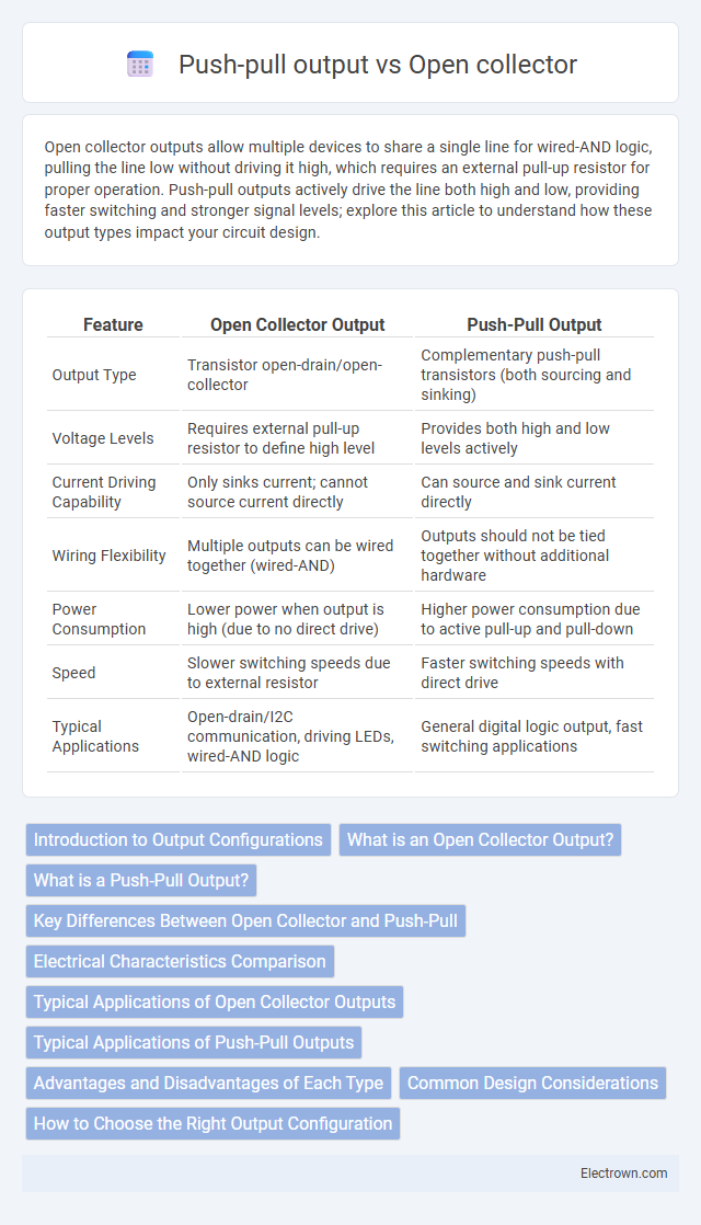
| Feature | Open Collector Output | Push-Pull Output |
|---|---|---|
| Output Type | Transistor open-drain/open-collector | Complementary push-pull transistors (both sourcing and sinking) |
| Voltage Levels | Requires external pull-up resistor to define high level | Provides both high and low levels actively |
| Current Driving Capability | Only sinks current; cannot source current directly | Can source and sink current directly |
| Wiring Flexibility | Multiple outputs can be wired together (wired-AND) | Outputs should not be tied together without additional hardware |
| Power Consumption | Lower power when output is high (due to no direct drive) | Higher power consumption due to active pull-up and pull-down |
| Speed | Slower switching speeds due to external resistor | Faster switching speeds with direct drive |
| Typical Applications | Open-drain/I2C communication, driving LEDs, wired-AND logic | General digital logic output, fast switching applications |
Introduction to Output Configurations
Open collector outputs allow multiple devices to share a common line for wired-AND logic by sinking current without driving it high, relying on an external pull-up resistor for voltage level. Push-pull outputs actively drive the line both high and low, providing faster switching speeds and stronger signal integrity. Selecting your output configuration depends on the specific application's need for signal control, noise immunity, and current driving capabilities.
What is an Open Collector Output?
An open collector output uses a transistor with its collector terminal left unconnected internally, requiring an external pull-up resistor to supply voltage and complete the circuit. This configuration allows multiple open collector outputs to be wired together for wired-AND logic or level shifting in mixed-voltage systems. Open collector outputs are commonly used in digital circuits for interfacing and signal isolation, providing flexibility in driving loads without exposing the internal transistor to high voltage.
What is a Push-Pull Output?
A push-pull output is a type of digital output stage where two transistors alternately drive the output high or low, enabling faster switching and stronger signal drive compared to open collector outputs. This configuration minimizes power dissipation and improves noise immunity, making it ideal for driving loads directly without external pull-up resistors. Understanding the advantages of push-pull outputs helps optimize your circuit design for efficiency and performance.
Key Differences Between Open Collector and Push-Pull
Open collector outputs use a transistor to sink current, requiring an external pull-up resistor to define the high-level voltage, enabling wired-AND connections and multiple device interfacing. Push-pull outputs actively drive both high and low states using complementary transistors, offering faster switching speeds and clearer voltage levels without external components. Key differences include the open collector's reliance on external pull-ups and its suitability for open-drain configurations, while push-pull provides stronger drive capability and reduced power consumption.
Electrical Characteristics Comparison
Open collector outputs feature a transistor that can pull the line low but requires an external pull-up resistor to reach a high level, resulting in slower rise times and higher power consumption. Push-pull outputs consist of complementary transistors actively driving both high and low states, offering faster switching speeds and lower output impedance for stronger signal integrity. Voltage levels in open collector setups depend on the external pull-up resistor and supply voltage, whereas push-pull outputs define voltage levels internally.
Typical Applications of Open Collector Outputs
Open collector outputs are widely used in applications requiring wired-AND logic, such as digital communication buses like I2C, where multiple devices share a common line without conflict. They are ideal for driving loads at different voltage levels or interfacing with higher voltage circuits by using an external pull-up resistor. Common scenarios include alarm systems, LED driving with multiplexing, and interfacing microcontrollers with relay or transistor switching circuits.
Typical Applications of Push-Pull Outputs
Push-pull outputs are commonly used in digital circuits requiring high-speed switching and efficient power delivery, such as microcontroller GPIO pins and communication interfaces like SPI and I2C. Their ability to actively drive both high and low states makes them ideal for applications needing fast response and precise voltage levels, including LED drivers and motor controllers. You benefit from their low power consumption and reduced signal distortion in these applications.
Advantages and Disadvantages of Each Type
Open collector outputs allow multiple devices to share a single line for wired-AND functions and can handle higher voltages than the device's logic level, offering flexibility in interfacing with various loads. However, they require an external pull-up resistor and tend to switch slower due to the resistor's influence, which can limit speed in high-frequency applications. Push-pull outputs provide faster switching speeds and stronger drive capability, allowing for clearer signal transitions without external resistors, but they are less tolerant of voltage level differences and cannot be wired together without risk of damage, limiting shared bus applications.
Common Design Considerations
Open collector and push-pull output stages differ primarily in their load driving capabilities and voltage requirements, influencing common design considerations. Open collector outputs require external pull-up resistors and are suitable for wired-AND configurations, making them ideal for level shifting and interfacing with different voltage domains. Your choice depends on factors such as desired load current, speed, and signal integrity requirements, with push-pull offering faster switching and stronger drive but lacking the open-drain compatibility of open collector designs.
How to Choose the Right Output Configuration
Choosing the right output configuration depends on your circuit's voltage levels and load requirements; open collector outputs are ideal for interfacing with different voltage domains and allow multiple outputs to be wired together for wired-AND logic. Push-pull outputs provide faster switching speeds and stronger drive capability, making them suitable for driving low-impedance loads directly. Your decision should also consider noise immunity and power consumption to ensure optimal performance in your specific application.
Open collector vs Push-pull output Infographic