Half Bridge and Full Bridge configurations differ mainly in how they control power delivery and handle voltage stress in circuits, with the Full Bridge offering better efficiency and higher power capacity for demanding applications. Explore the rest of the article to understand which bridge topology suits Your specific electronic design needs.
Table of Comparison
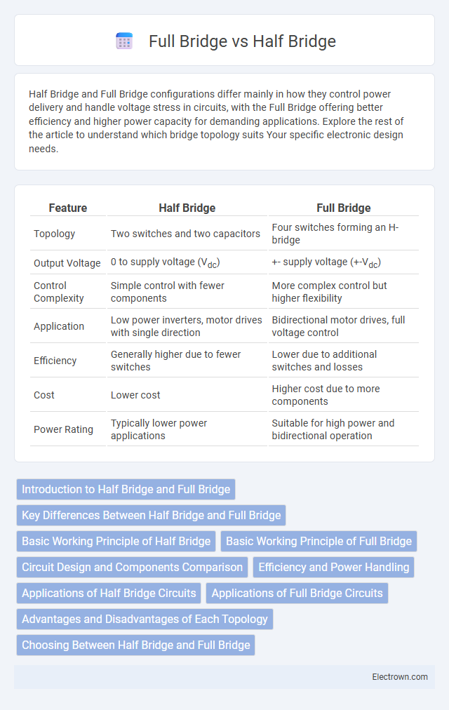
| Feature | Half Bridge | Full Bridge |
|---|---|---|
| Topology | Two switches and two capacitors | Four switches forming an H-bridge |
| Output Voltage | 0 to supply voltage (Vdc) | +- supply voltage (+-Vdc) |
| Control Complexity | Simple control with fewer components | More complex control but higher flexibility |
| Application | Low power inverters, motor drives with single direction | Bidirectional motor drives, full voltage control |
| Efficiency | Generally higher due to fewer switches | Lower due to additional switches and losses |
| Cost | Lower cost | Higher cost due to more components |
| Power Rating | Typically lower power applications | Suitable for high power and bidirectional operation |
Introduction to Half Bridge and Full Bridge
Half Bridge and Full Bridge configurations are essential in power electronics for controlling voltage and current through load devices. The Half Bridge uses two switches and two capacitors to generate a balanced voltage output, while the Full Bridge employs four switches to provide greater control and the ability to reverse the polarity of the output voltage. Understanding these topologies helps you optimize efficiency and performance in applications such as motor drives and DC-DC converters.
Key Differences Between Half Bridge and Full Bridge
Half bridge circuits use two switches and can control power to a load in one direction, while full bridge circuits employ four switches enabling bidirectional control and higher power handling. Full bridges provide greater voltage output and improved efficiency in motor control applications compared to half bridges. The choice between half and full bridge depends on application needs including power requirements, control complexity, and desired output waveform.
Basic Working Principle of Half Bridge
A half bridge converter uses two switches connected in series across a voltage supply to alternately apply voltage to the load, creating an alternating output signal. This configuration allows for efficient voltage conversion with fewer components and simpler control compared to a full bridge. The basic working principle relies on switching each transistor on and off in a complementary manner to maintain continuous power delivery without short circuits.
Basic Working Principle of Full Bridge
The full bridge, also known as an H-bridge, operates by using four switches arranged in an H configuration to control the direction and magnitude of current through a load, enabling bidirectional control of DC motors or other inductive loads. When diagonally opposite switches are activated simultaneously, current flows through the load in one direction, and reversing the active switches reverses the current flow, allowing for forward and reverse operation. This efficient switching mechanism provides precise control over motor speed and torque, making full bridges essential in applications requiring dynamic motor control.
Circuit Design and Components Comparison
Half Bridge circuits utilize two switches and two capacitors to control power flow, offering simpler design and fewer components, which reduces cost and complexity. Full Bridge configurations employ four switches arranged in an H-bridge layout, enabling bidirectional current flow and increased control over load voltage polarity, making them suitable for applications requiring higher power and flexibility. The component count and arrangement in Full Bridges result in more complex driving circuitry but provide enhanced performance for motor control and power conversion tasks.
Efficiency and Power Handling
Full bridge configurations typically offer higher efficiency and better power handling compared to half bridge designs due to their ability to utilize both power supply rails fully. Half bridge circuits are simpler but generally handle lower power and can have increased conduction losses, reducing overall efficiency. When designing your system, choosing a full bridge can maximize performance in high-power applications where efficiency is critical.
Applications of Half Bridge Circuits
Half bridge circuits are commonly used in power electronics for efficient DC-DC converters, motor control in brushless DC motors, and as part of Class D audio amplifiers due to their ability to handle moderate power levels with fewer components. They enable precise voltage regulation in applications such as battery chargers and photovoltaic inverters, where balanced switching reduces electromagnetic interference. Half bridge topologies are favored in space-constrained devices requiring cost-effective, high-frequency operation with improved switching efficiency.
Applications of Full Bridge Circuits
Full bridge circuits are widely used in applications requiring precise control of power delivery, such as in DC motor drives, where they allow for bidirectional rotation and speed regulation. They are essential in power inverters, enabling efficient AC output from DC sources, and in pulse width modulation (PWM) techniques for controlling voltage and current. Your projects involving high-power and high-precision control benefit significantly from the versatility of full bridge configurations.
Advantages and Disadvantages of Each Topology
Half bridge topology offers simpler design and lower component count, resulting in reduced cost and smaller size but may suffer from limited voltage output and increased stress on switches. Full bridge topology provides higher output voltage and improved efficiency through better utilization of switches, though it entails greater complexity and higher component costs. Choosing between them depends on balancing efficiency versus cost constraints in power conversion applications.
Choosing Between Half Bridge and Full Bridge
Choosing between a half bridge and full bridge depends on your power and efficiency requirements; a half bridge offers simpler design and lower cost for moderate loads, while a full bridge delivers higher output voltage and greater power handling for demanding applications. Your choice should consider factors like switching frequency, voltage levels, and thermal management, as full bridges typically provide better performance in high-power scenarios. Optimizing your design with the right configuration ensures improved system reliability and energy efficiency.
Half Bridge vs Full Bridge Infographic