The E-plane and H-plane refer to the principal planes used to describe the radiation pattern of antennas, where the E-plane represents the plane containing the electric field vector, and the H-plane corresponds to the plane of the magnetic field vector. Understanding the differences between these planes is essential for optimizing antenna performance and radiation characteristics, so explore the rest of the article to enhance your knowledge.
Table of Comparison
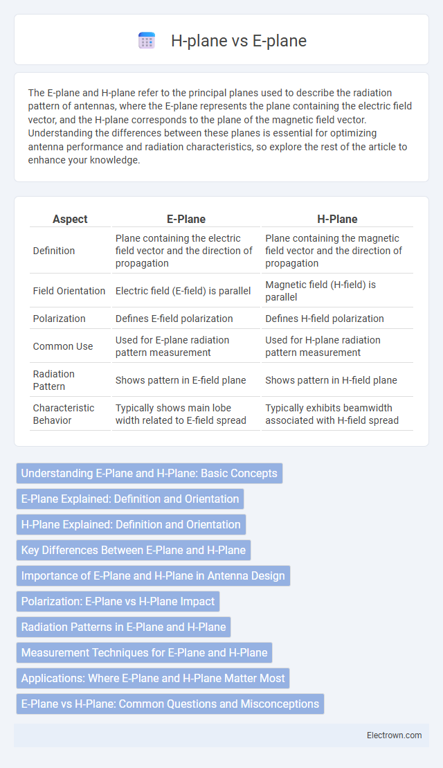
| Aspect | E-Plane | H-Plane |
|---|---|---|
| Definition | Plane containing the electric field vector and the direction of propagation | Plane containing the magnetic field vector and the direction of propagation |
| Field Orientation | Electric field (E-field) is parallel | Magnetic field (H-field) is parallel |
| Polarization | Defines E-field polarization | Defines H-field polarization |
| Common Use | Used for E-plane radiation pattern measurement | Used for H-plane radiation pattern measurement |
| Radiation Pattern | Shows pattern in E-field plane | Shows pattern in H-field plane |
| Characteristic Behavior | Typically shows main lobe width related to E-field spread | Typically exhibits beamwidth associated with H-field spread |
Understanding E-Plane and H-Plane: Basic Concepts
E-plane represents the plane containing the electric field vector and the direction of wave propagation, crucial for analyzing antenna radiation patterns and polarization. H-plane, on the other hand, contains the magnetic field vector and propagation direction, often used to determine antenna beamwidth and gain. Understanding these planes helps you optimize antenna design and accurately predict electromagnetic wave behavior in wireless communication systems.
E-Plane Explained: Definition and Orientation
The E-plane represents the plane containing the electric field vector and the direction of wave propagation in an antenna pattern. Its orientation is typically defined as the plane where the electric field is maximized, often used to analyze antenna radiation characteristics. Understanding the E-plane helps you optimize antenna placement and performance by accurately assessing polarization and beamwidth.
H-Plane Explained: Definition and Orientation
The H-plane, or magnetic plane, refers to the plane containing the magnetic field vector and the direction of maximum radiation in an antenna's radiation pattern. It is perpendicular to the E-plane, which contains the electric field vector, making the H-plane crucial for understanding the antenna's horizontal radiation characteristics. Your analysis of antenna patterns will be more precise by distinguishing the orientation and behavior of the H-plane in various antenna designs.
Key Differences Between E-Plane and H-Plane
E-plane and H-plane refer to two principal planes in antenna radiation patterns, where the E-plane represents the plane containing the electric field vector and the direction of maximum radiation, while the H-plane contains the magnetic field vector and the direction of maximum radiation. Key differences include their polarization orientation--with the E-plane being aligned with the electric field and the H-plane with the magnetic field--and their distinct radiation characteristics affecting antenna design and analysis. Understanding these differences helps you optimize antenna performance for specific applications by accurately interpreting radiation patterns.
Importance of E-Plane and H-Plane in Antenna Design
E-plane and H-plane are critical in antenna design because they represent the principal planes of polarization and radiation patterns, directly influencing antenna performance and beam shaping. Understanding these planes allows accurate control of antenna gain, directivity, and impedance matching, optimizing signal strength and coverage for your specific application. Precise manipulation of E-plane and H-plane characteristics ensures efficient antenna operation in wireless communication, radar, and broadcasting systems.
Polarization: E-Plane vs H-Plane Impact
E-plane polarization refers to the orientation of the electric field vector, typically aligned with the plane of the antenna's electric field, whereas H-plane polarization involves the magnetic field vector's orientation perpendicular to the E-plane. Your antenna's radiation pattern, gain, and cross-polarization levels can significantly vary depending on whether the E-plane or H-plane is dominant, affecting signal clarity and strength. Understanding the impact of E-plane versus H-plane polarization is crucial for optimizing antenna performance and minimizing interference in wireless communication systems.
Radiation Patterns in E-Plane and H-Plane
Radiation patterns in the E-plane exhibit the electric field distribution of an antenna, typically showing the main lobe and side lobes with respect to the electric field vector orientation. In contrast, the H-plane radiation pattern represents the magnetic field distribution, often illustrating the antenna's azimuthal coverage with respect to the magnetic field vector. Understanding both E-plane and H-plane patterns is crucial for optimizing Your antenna's directional performance and beamwidth characteristics.
Measurement Techniques for E-Plane and H-Plane
Measurement techniques for E-plane and H-plane primarily involve the use of antenna test ranges and network analyzers to evaluate radiation patterns, gain, and impedance. The E-plane measurements focus on the electric field polarization, typically conducted by rotating the antenna around the horizontal axis, while H-plane measurements assess the magnetic field polarization through rotation around the vertical axis. Accurate calibration and alignment in your setup ensure precise characterization of antenna performance in both planes.
Applications: Where E-Plane and H-Plane Matter Most
E-plane and H-plane play crucial roles in the design and performance of antennas, microwave circuits, and waveguides, where directional signal control is essential. Your choice between E-plane and H-plane components impacts beam shaping, polarization, and impedance matching in radar systems, satellite communications, and wireless networks. Optimizing these planes ensures efficient signal propagation and minimal interference in highly directional applications.
E-Plane vs H-Plane: Common Questions and Misconceptions
The E-plane and H-plane refer to the electric and magnetic field orientations in antenna radiation patterns, crucial for understanding antenna polarization and directivity. Common misconceptions include confusing the planes with physical antenna structures or assuming they always align perpendicularly, whereas their orientation depends on the antenna type and polarization mode. Your grasp of these concepts enhances antenna design accuracy and improves communication system performance.
E-plane vs H-plane Infographic