Inductive loads, such as motors and transformers, generate magnetic fields that cause voltage spikes when switched off, requiring specialized switching methods to prevent damage. Resistive loads, like heaters or incandescent bulbs, have straightforward switching characteristics with no significant voltage spikes, making them easier to control; discover more about how your choice of switching impacts device performance and reliability in the full article.
Table of Comparison
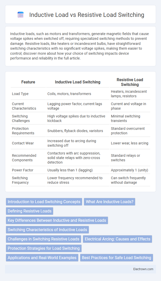
| Feature | Inductive Load Switching | Resistive Load Switching |
|---|---|---|
| Load Type | Coils, motors, transformers | Heaters, incandescent lamps, resistors |
| Current Characteristics | Lagging power factor, current lags voltage | Current and voltage in phase |
| Switching Challenges | High voltage spikes due to inductive kickback | Minimal switching transients |
| Protection Requirements | Snubbers, flyback diodes, varistors | Standard overcurrent protection |
| Contact Wear | Increased due to arcing during switching off | Lower wear, less arcing |
| Recommended Components | Contactors with arc suppression, solid state relays with zero-cross detection | Standard relays or switches |
| Power Factor | Usually less than 1 (lagging) | Approximately 1 (unity) |
| Switching Frequency | Lower frequency recommended to reduce stress | Can switch frequently without damage |
Introduction to Load Switching Concepts
Inductive load switching involves controlling devices like motors, transformers, or solenoids that store energy in magnetic fields, causing voltage spikes when switched off. Resistive load switching controls devices such as heaters or incandescent bulbs, which convert electrical energy directly into heat without causing significant voltage transients. Understanding these differences is crucial for selecting appropriate switching components to protect your circuits and ensure reliable operation.
What Are Inductive Loads?
Inductive loads are electrical devices that primarily consist of coils or windings, such as motors, transformers, and solenoids, which store energy in a magnetic field when current flows through them. Unlike resistive loads, which convert electrical energy directly into heat, inductive loads generate back electromotive force (EMF) during switching, causing voltage spikes that can damage switching components. Understanding these characteristics is crucial for Your equipment's protection and efficient switching in circuits involving inductive loads.
Defining Resistive Loads
Resistive loads primarily consist of electrical components that convert electric energy directly into heat, such as incandescent light bulbs, heaters, and electric stoves. These loads exhibit a linear relationship between voltage and current, resulting in purely resistive impedance with no phase difference. This characteristic simplifies switching operations, reducing issues like voltage spikes and enabling more straightforward control compared to inductive loads.
Key Differences Between Inductive and Resistive Loads
Inductive loads, such as motors and transformers, store energy in magnetic fields, causing current to lag voltage and creating inrush currents during switching, whereas resistive loads like heaters and incandescent bulbs convert electrical energy directly into heat, maintaining a linear current-voltage relationship. Switching inductive loads requires consideration of back EMF and may necessitate snubber circuits or RC networks to suppress voltage spikes, while resistive loads experience minimal switching transients, simplifying control circuit design. The switching devices for inductive loads must handle higher stress due to energy stored in the magnetic field, contrasting with resistive loads where switching is mostly defined by the device's current and voltage ratings.
Switching Characteristics of Inductive Loads
Inductive loads, such as motors and transformers, exhibit unique switching characteristics due to energy stored in their magnetic fields, causing voltage spikes and longer current decay times during switching. These characteristics increase stress on switching devices, requiring snubber circuits or flyback diodes to protect against high-voltage transients and ensure reliable operation. When switching inductive loads, your system must manage these transient conditions to avoid damage and maintain performance.
Challenges in Switching Resistive Loads
Switching resistive loads presents challenges such as inrush current surges that can cause contact wear and heat buildup in switching devices, reducing their lifespan. The lack of voltage spikes typical in inductive loads means arc suppression relies primarily on the device's inherent properties, which may cause faster degradation under frequent switching. Proper device selection and thermal management are crucial to ensure Your system maintains reliability and longevity when handling resistive load switching.
Electrical Arcing: Causes and Effects
Electrical arcing during switching of inductive loads occurs due to the sudden collapse of the magnetic field, generating high voltage spikes that can ionize the air gap and create a sustained arc. In resistive load switching, arcing is typically minimal because current changes smoothly without significant voltage transients. Your equipment may suffer contact erosion, increased wear, and potential failure when arcing is frequent, particularly with inductive loads, making appropriate switching methods and protective devices essential.
Protection Strategies for Load Switching
Effective protection strategies for switching inductive loads include using snubber circuits, RC networks, or flyback diodes to suppress voltage spikes caused by energy stored in the load's magnetic field. In contrast, resistive load switching primarily requires simple overcurrent protection and thermal management due to their stable resistive nature without significant transient voltages. Implementing appropriately rated contactors or solid-state relays with built-in surge suppression enhances overall system reliability and prevents premature component failure in both load types.
Applications and Real-World Examples
Inductive load switching is common in applications involving motors, transformers, and solenoids where energy storage in magnetic fields requires careful handling to prevent voltage spikes. Resistive load switching typically occurs in heating elements, incandescent lighting, and simple electrical resistors, where current regulation is straightforward due to the absence of stored energy. Real-world examples include industrial motor controls for inductive loads and household electric heaters or toaster ovens as typical resistive load devices.
Best Practices for Safe Load Switching
Safe switching of inductive loads requires implementing flyback diodes or snubber circuits to manage voltage spikes caused by the collapsing magnetic field, preventing damage to switching devices. Resistive load switching benefits from straightforward on/off control with minimal transient effects, but ensuring proper current ratings and thermal management is essential for longevity. You should always select switching components rated for the specific load type and incorporate protective measures like surge suppression to optimize reliability and safety.
Inductive load vs Resistive load switching Infographic