The source follower offers high input impedance and voltage buffering, making it ideal for impedance matching, while the common gate configuration provides low input impedance and is preferred for high-frequency applications and low-noise amplification. Explore the rest of the article to understand which transistor stage best suits your specific circuit needs.
Table of Comparison
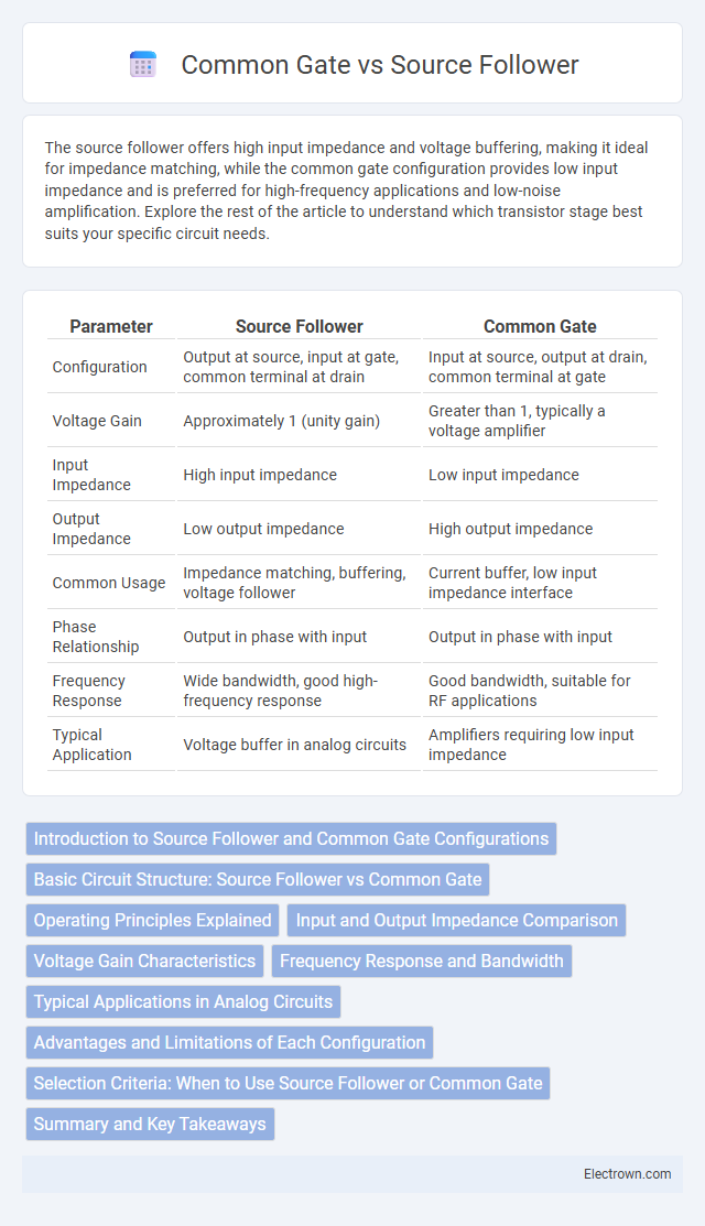
| Parameter | Source Follower | Common Gate |
|---|---|---|
| Configuration | Output at source, input at gate, common terminal at drain | Input at source, output at drain, common terminal at gate |
| Voltage Gain | Approximately 1 (unity gain) | Greater than 1, typically a voltage amplifier |
| Input Impedance | High input impedance | Low input impedance |
| Output Impedance | Low output impedance | High output impedance |
| Common Usage | Impedance matching, buffering, voltage follower | Current buffer, low input impedance interface |
| Phase Relationship | Output in phase with input | Output in phase with input |
| Frequency Response | Wide bandwidth, good high-frequency response | Good bandwidth, suitable for RF applications |
| Typical Application | Voltage buffer in analog circuits | Amplifiers requiring low input impedance |
Introduction to Source Follower and Common Gate Configurations
The source follower configuration, also known as the common drain amplifier, provides high input impedance and unity voltage gain, making it ideal for impedance matching and voltage buffering applications. The common gate configuration features low input impedance and high output impedance, commonly used in high-frequency amplifiers and current buffer stages. Both configurations are essential in analog circuit design, offering distinct trade-offs in gain, input-output impedance, and frequency response.
Basic Circuit Structure: Source Follower vs Common Gate
The source follower circuit features a MOSFET with the input applied to the gate, the output taken from the source, and the common terminal connected to the gate's reference, typically ground for the source follower configuration. In contrast, the common gate circuit applies the input signal directly to the source terminal, with the gate being common and usually grounded or biased at a fixed voltage, while the output is taken from the drain. This fundamental structural difference influences their respective voltage gain, input, and output impedance characteristics in analog circuit design.
Operating Principles Explained
The source follower operates as a voltage buffer with high input impedance and low output impedance, primarily using a MOSFET with its source as the output and the gate as the input, enabling voltage gain close to unity. The common gate amplifier, by contrast, features the gate terminal grounded and input at the source, allowing high-frequency operation with low input capacitance and moderate voltage gain. Both configurations leverage transistor characteristics differently: the source follower emphasizes impedance matching and signal buffering, while the common gate focuses on input current control and frequency response.
Input and Output Impedance Comparison
Source follower circuits typically exhibit high input impedance and low output impedance, making them ideal for voltage buffering and impedance matching applications. In contrast, common gate configurations have low input impedance and high output impedance, which suits them for current buffering and high-frequency amplification tasks. Understanding this contrast enables you to select the appropriate transistor stage for optimal signal integrity and circuitry performance.
Voltage Gain Characteristics
Source followers exhibit voltage gain close to unity, typically slightly less than one due to the source degeneration effect, offering high input impedance and low output impedance, making them ideal for impedance buffering. Common gate configurations provide voltage gain greater than one, leveraging low input impedance at the gate and high output impedance, which benefits high-frequency applications and voltage amplification stages. The gain in common gate amplifiers is primarily determined by the transconductance (gm) and load resistance, while the source follower relies heavily on the transistor's intrinsic gain and load conditions.
Frequency Response and Bandwidth
Source follower amplifiers typically offer higher bandwidth and better high-frequency response due to their low output impedance, which minimizes signal distortion at high frequencies. Common gate stages present a wider input bandwidth and improved high-frequency performance compared to common source, making them ideal for RF applications with high-frequency signals. You should choose a source follower for buffering and voltage gain with wide bandwidth, while a common gate excels in driving low-impedance loads with a broad frequency response.
Typical Applications in Analog Circuits
Source followers are typically used in buffer stages for impedance matching and voltage level shifting due to their high input impedance and unity voltage gain. Common gate configurations are preferred in high-frequency amplifier designs and current buffer applications because of their low input impedance and high bandwidth. Your choice between these topologies depends on whether voltage buffering or wideband signal amplification is the primary concern in your analog circuit.
Advantages and Limitations of Each Configuration
Source follower amplifiers offer high input impedance and low output impedance, making them ideal for impedance matching and voltage buffering, but their voltage gain is slightly less than unity. Common gate amplifiers provide low input impedance and high voltage gain with good frequency response, suitable for high-frequency applications, but their input matching can be challenging and power consumption tends to be higher. Your choice depends on whether you prioritize input/output impedance characteristics or gain and frequency response for your specific circuit requirements.
Selection Criteria: When to Use Source Follower or Common Gate
Source follower amplifiers offer high input impedance and unity voltage gain, making them ideal for buffering signals where minimal loading is essential. Common gate configurations provide low input impedance and high voltage gain, suitable for high-frequency applications and impedance matching in RF circuits. Your choice depends on the need for input impedance, gain, and frequency response requirements within your specific electronic design.
Summary and Key Takeaways
Source followers offer high input impedance and low output impedance, making them ideal for voltage buffering and impedance matching in analog circuits. Common gate amplifiers provide low input impedance and high-frequency performance, often used in RF stages and current buffering. Choosing between source follower and common gate depends on the desired input/output impedance and frequency response requirements.
Source follower vs common gate Infographic