Resistor Transistor Logic (RTL) uses resistors and transistors to create basic logic gates, offering simplicity but limited speed and power efficiency, while Diode Transistor Logic (DTL) incorporates diodes and transistors for improved noise immunity and better switching performance. Explore the rest of this article to understand how these two logic families compare and which is best suited for your electronic design needs.
Table of Comparison
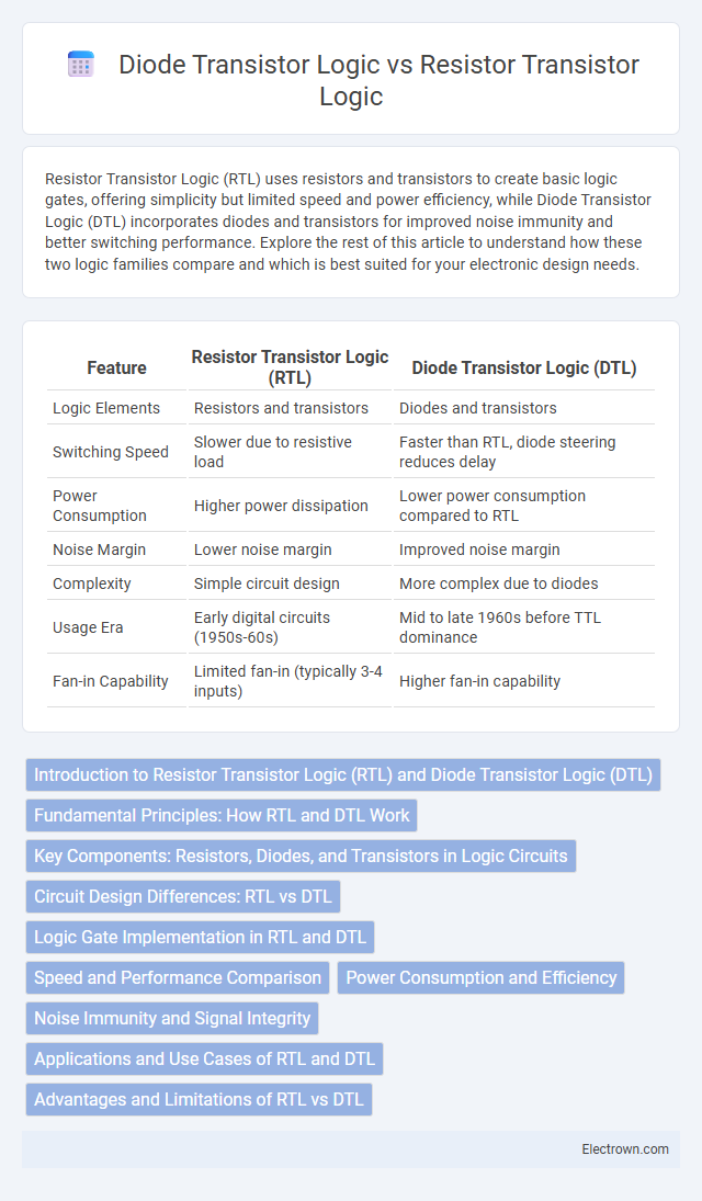
| Feature | Resistor Transistor Logic (RTL) | Diode Transistor Logic (DTL) |
|---|---|---|
| Logic Elements | Resistors and transistors | Diodes and transistors |
| Switching Speed | Slower due to resistive load | Faster than RTL, diode steering reduces delay |
| Power Consumption | Higher power dissipation | Lower power consumption compared to RTL |
| Noise Margin | Lower noise margin | Improved noise margin |
| Complexity | Simple circuit design | More complex due to diodes |
| Usage Era | Early digital circuits (1950s-60s) | Mid to late 1960s before TTL dominance |
| Fan-in Capability | Limited fan-in (typically 3-4 inputs) | Higher fan-in capability |
Introduction to Resistor Transistor Logic (RTL) and Diode Transistor Logic (DTL)
Resistor Transistor Logic (RTL) uses resistors as the input network combined with transistors to perform logical operations, offering simple and cost-effective digital circuits. Diode Transistor Logic (DTL) integrates diodes for input logic gating and transistors for amplification, providing faster switching speeds and improved noise margins compared to RTL. Your choice between RTL and DTL influences factors such as speed, power consumption, and circuit complexity in digital design.
Fundamental Principles: How RTL and DTL Work
Resistor Transistor Logic (RTL) operates by using resistors as input network elements to perform logic functions, where transistors switch between saturation and cutoff states to represent binary signals. Diode Transistor Logic (DTL) employs diodes at the input to create an AND function, with transistors used for amplification and inversion of the logic signal. Both RTL and DTL circuits rely on transistor switching, but RTL uses resistor-based input combinations while DTL leverages diode-connected inputs for improved logic gating efficiency.
Key Components: Resistors, Diodes, and Transistors in Logic Circuits
Resistor transistor logic (RTL) primarily uses resistors and transistors as its key components, where resistors function as load elements and transistors act as switches to perform logic operations. Diode transistor logic (DTL) incorporates diodes for input logic gating and transistors for amplification and switching, with diodes responsible for logical AND and OR functions before transistor inversion. The use of diodes in DTL allows improved logic gate configurations by reducing the number of resistors needed compared to RTL, resulting in enhanced speed and reliability in early digital circuits.
Circuit Design Differences: RTL vs DTL
Resistor Transistor Logic (RTL) circuits use resistors as the primary input network components, controlling current to the transistor base, which results in simple and low-cost designs but higher power consumption and slower switching speeds. Diode Transistor Logic (DTL) replaces resistors with diode networks at the input stage, providing improved noise margins and faster switching by creating distinct voltage levels before transistor amplification. The key design difference lies in the input section: RTL relies on resistors for input current limiting, while DTL employs diode arrangements for logic gating, enhancing performance and noise immunity.
Logic Gate Implementation in RTL and DTL
Resistor-transistor logic (RTL) implements logic gates by using resistors as input networks to control the base of transistors for switching, enabling basic Boolean operations like AND and OR with simple voltage divider circuits. Diode-transistor logic (DTL) improves gate performance by replacing the input resistor network with diodes that perform the logical gating before the transistor stage, offering faster switching speeds and better noise margins compared to RTL. RTL gates consume more power and exhibit slower speed due to resistor loading, while DTL gates provide enhanced fan-in capability and improved signal integrity in digital circuits.
Speed and Performance Comparison
Resistor Transistor Logic (RTL) circuits generally exhibit slower switching speeds compared to Diode Transistor Logic (DTL) due to the resistors causing greater voltage drops and power dissipation. DTL improves performance by utilizing diodes for input gating, allowing faster transition times and more reliable noise margins in digital circuits. Understanding these distinctions helps you select the optimal logic family for speed-critical applications.
Power Consumption and Efficiency
Resistor Transistor Logic (RTL) generally consumes more power than Diode Transistor Logic (DTL) due to its constant current flow through resistors, leading to lower efficiency in large-scale circuits. DTL improves efficiency by using diodes to control current paths, reducing power dissipation during switching. For your designs, selecting DTL may offer better power management and improved overall circuit efficiency compared to RTL.
Noise Immunity and Signal Integrity
Resistor Transistor Logic (RTL) offers moderate noise immunity but suffers from voltage drop issues across resistors, which can degrade signal integrity at higher frequencies. Diode Transistor Logic (DTL) enhances noise margins through diode clamping, resulting in better noise immunity and improved signal integrity compared to RTL. The use of diodes in DTL reduces voltage noise susceptibility and stabilizes switching thresholds, leading to cleaner digital transitions in logic circuits.
Applications and Use Cases of RTL and DTL
Resistor Transistor Logic (RTL) is widely used in low-speed, low-cost digital circuits such as simple logic gates and early computing devices due to its straightforward design and minimal component requirements. Diode Transistor Logic (DTL) finds application in medium-speed digital circuits including basic combinational logic used in early digital systems and control circuits where improved switching speed over RTL is needed. Your choice between RTL and DTL depends on speed requirements and complexity, with DTL typically preferred in cases demanding better noise margins and faster operation.
Advantages and Limitations of RTL vs DTL
Resistor Transistor Logic (RTL) offers simplicity and low component count, providing fast switching speeds, but it suffers from higher power consumption and limited noise margins compared to Diode Transistor Logic (DTL). DTL improves noise immunity and has better fan-out capability due to the use of diodes for input logic gating but introduces slower switching speeds and increased circuit complexity. Your choice between RTL and DTL depends on the specific requirements for speed, power efficiency, and signal integrity in digital circuit design.
Resistor transistor logic vs Diode transistor logic Infographic