Emitter coupled pairs offer high-speed switching with low voltage swings ideal for analog circuits, while differential pairs provide superior noise immunity and accurate signal amplification in balanced systems. Learn how choosing the right pair affects Your circuit performance in the rest of this article.
Table of Comparison
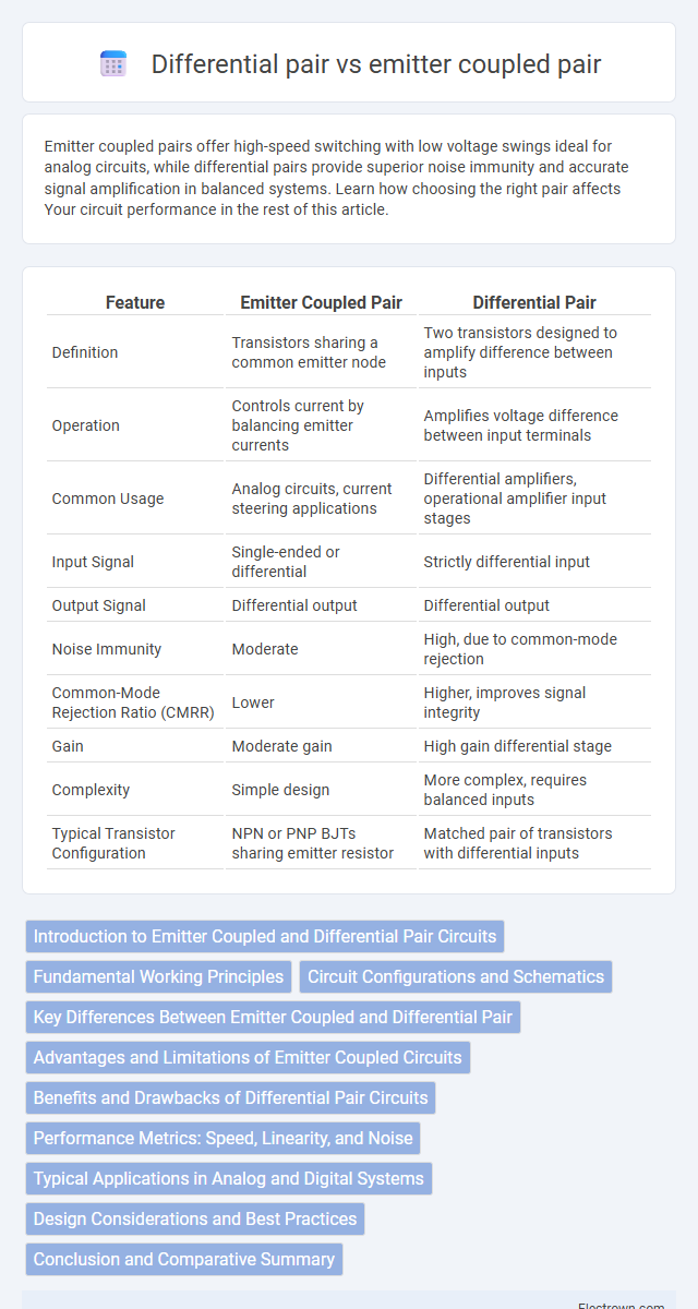
| Feature | Emitter Coupled Pair | Differential Pair |
|---|---|---|
| Definition | Transistors sharing a common emitter node | Two transistors designed to amplify difference between inputs |
| Operation | Controls current by balancing emitter currents | Amplifies voltage difference between input terminals |
| Common Usage | Analog circuits, current steering applications | Differential amplifiers, operational amplifier input stages |
| Input Signal | Single-ended or differential | Strictly differential input |
| Output Signal | Differential output | Differential output |
| Noise Immunity | Moderate | High, due to common-mode rejection |
| Common-Mode Rejection Ratio (CMRR) | Lower | Higher, improves signal integrity |
| Gain | Moderate gain | High gain differential stage |
| Complexity | Simple design | More complex, requires balanced inputs |
| Typical Transistor Configuration | NPN or PNP BJTs sharing emitter resistor | Matched pair of transistors with differential inputs |
Introduction to Emitter Coupled and Differential Pair Circuits
Emitter coupled circuits use bipolar junction transistors (BJTs) arranged to share a common emitter resistor, forming a current-steering network ideal for high-speed analog switching. Differential pair circuits consist of two transistors with connected emitters that compare input signals, providing high gain and common-mode noise rejection essential for precise amplification. Your choice between these configurations depends on the required balance between speed, linearity, and noise performance in analog signal processing.
Fundamental Working Principles
Emitter-coupled pairs operate by sharing a constant current source between two transistors, with the input signal controlling the differential voltage across the emitters, causing current steering that results in differential output signals. Differential pairs consist of two matched transistors that compare input voltages, producing an output corresponding to the voltage difference at their bases, amplifying the differential signal while rejecting common-mode noise. Both topologies rely on transistor matching and current splitting for linearity and high gain in analog circuits such as operational amplifiers and comparators.
Circuit Configurations and Schematics
Emitter coupled pairs utilize bipolar junction transistors (BJTs) with emitters tied together and connected to a constant current source, forming a classic long-tailed pair configuration ideal for differential amplification. Differential pairs can be implemented with BJTs or MOSFETs, where the schematics typically show two transistors sharing a common emitter or source node, optimizing input signal difference detection and providing high gain and common-mode rejection. Circuit configurations of emitter coupled pairs emphasize balanced transistor operation and a stable current reference, while differential pair schematics highlight symmetrical transistor arrangement for enhanced linearity and noise immunity.
Key Differences Between Emitter Coupled and Differential Pair
Emitter coupled pairs utilize a shared emitter resistor to control current flow, providing a stable operating point and improved linearity, while differential pairs rely on separate current paths for each transistor. The differential pair excels in common-mode noise rejection due to its symmetrical structure, whereas emitter coupled pairs offer faster switching speeds and higher gain. Design considerations favor emitter coupled pairs for high-frequency applications and differential pairs for precise, low-noise signal amplification.
Advantages and Limitations of Emitter Coupled Circuits
Emitter coupled circuits offer high gain and improved linearity by utilizing transistor pairs that share a common emitter resistor, which enhances signal stability and reduces distortion. These circuits provide excellent frequency response and noise immunity, making them suitable for high-speed analog applications. However, their main limitations include increased power consumption and sensitivity to transistor mismatches, which can impact overall circuit performance and reliability.
Benefits and Drawbacks of Differential Pair Circuits
Differential pair circuits offer improved noise immunity and increased signal integrity by processing two complementary signals, which cancels out common-mode interference and enhances performance in high-speed and low-voltage applications. However, these circuits require precise matching of components and increased layout complexity, leading to higher design efforts and silicon area consumption compared to single-ended emitter coupled configurations. Your choice depends on balancing the need for robustness against noise with constraints like power, area, and design complexity.
Performance Metrics: Speed, Linearity, and Noise
Emitter coupled pairs exhibit higher speed due to their low voltage swing and fast switching capabilities, making them ideal for high-frequency applications. Differential pairs offer superior linearity and reduced distortion, enhancing signal integrity in analog circuits. Your choice depends on whether speed or signal fidelity is the priority, as emitter coupled configurations may introduce more noise compared to the inherently noise-reducing differential pair design.
Typical Applications in Analog and Digital Systems
Emitter coupled pairs are commonly used in high-speed analog circuits such as operational amplifiers and analog multipliers due to their excellent linearity and fast switching capabilities. Differential pairs find widespread application in digital systems like logic gates, comparators, and data converters, providing improved noise immunity and signal integrity. Your choice between these configurations depends on the balance of speed, accuracy, and noise performance required by the specific analog or digital application.
Design Considerations and Best Practices
Emitter coupled pairs offer low voltage operation and high transconductance, making them ideal for high-frequency analog circuit design, while differential pairs provide superior common-mode noise rejection and linearity crucial for precision analog applications. Design considerations include choosing appropriate bias currents for emitter coupled pairs to balance speed and power consumption, whereas differential pairs require careful matching of transistor pairs to minimize offset and distortion. Best practices emphasize layout symmetry, minimizing parasitic capacitances, and ensuring thermal stability to optimize performance in both configurations.
Conclusion and Comparative Summary
Emitter coupled pairs offer faster switching speeds and better linearity due to constant current operation, making them ideal for high-frequency analog circuits. Differential pairs excel in noise rejection and voltage gain stability, providing reliable performance in low-frequency and mixed-signal applications. Your choice depends on the specific requirements of speed, noise tolerance, and linearity in the target circuit design.
Emitter coupled vs differential pair Infographic