Pass transistors use a single transistor to control signal flow but suffer from voltage drop issues, limiting their ability to pass full voltage levels efficiently; transmission gates combine both n-channel and p-channel MOSFETs, providing better voltage levels and reduced signal degradation. Explore the detailed comparison to understand which approach best suits Your circuit design needs.
Table of Comparison
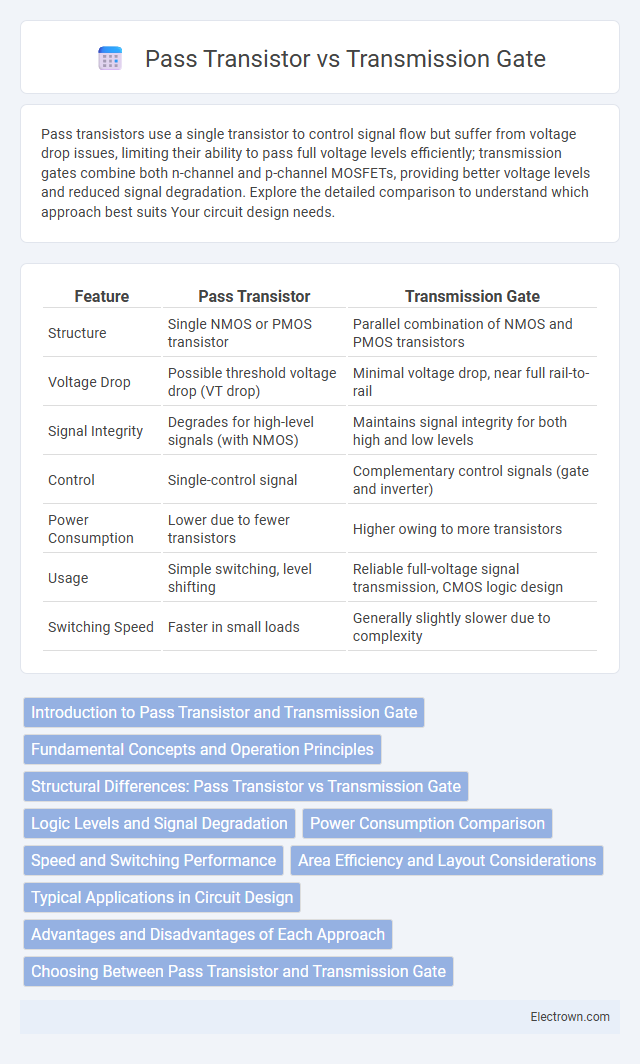
| Feature | Pass Transistor | Transmission Gate |
|---|---|---|
| Structure | Single NMOS or PMOS transistor | Parallel combination of NMOS and PMOS transistors |
| Voltage Drop | Possible threshold voltage drop (VT drop) | Minimal voltage drop, near full rail-to-rail |
| Signal Integrity | Degrades for high-level signals (with NMOS) | Maintains signal integrity for both high and low levels |
| Control | Single-control signal | Complementary control signals (gate and inverter) |
| Power Consumption | Lower due to fewer transistors | Higher owing to more transistors |
| Usage | Simple switching, level shifting | Reliable full-voltage signal transmission, CMOS logic design |
| Switching Speed | Faster in small loads | Generally slightly slower due to complexity |
Introduction to Pass Transistor and Transmission Gate
Pass transistors are MOSFET devices used to control signal flow by allowing or blocking voltage levels based on input gate signals, typically resulting in reduced transistor counts and lower power consumption in digital circuits. Transmission gates combine complementary NMOS and PMOS transistors to create bidirectional switches with minimal voltage degradation and improved signal integrity, widely used in CMOS technology for multiplexers and logic circuits. Both pass transistors and transmission gates are fundamental building blocks in efficient logic design, offering trade-offs between simplicity, voltage levels, and overall performance.
Fundamental Concepts and Operation Principles
A pass transistor operates by using a single MOS transistor to control the flow of signals, allowing data to pass through when the transistor is on, but may suffer from voltage drop due to threshold voltage limitations. A transmission gate consists of parallel nMOS and pMOS transistors controlled by complementary signals, enabling signal transmission without voltage degradation and offering full rail-to-rail voltage swing. The fundamental difference lies in the transmission gate's ability to pass both strong logic high and low levels effectively, while the pass transistor is typically limited by threshold voltage loss.
Structural Differences: Pass Transistor vs Transmission Gate
Pass transistors use a single MOSFET to control signal transmission, employing only either an NMOS or PMOS device, which limits voltage swing and can cause threshold voltage drops. Transmission gates consist of parallel NMOS and PMOS transistors controlled by complementary signals, enabling full voltage swing and improved signal integrity. Your choice between the two affects circuit performance, as transmission gates generally offer better structural robustness for switching applications.
Logic Levels and Signal Degradation
Pass transistors often suffer from voltage threshold drops, causing degraded logic levels and incomplete signal transmission in digital circuits. Transmission gates avoid this issue by using parallel NMOS and PMOS transistors, ensuring full voltage swing and preserving signal integrity. Optimizing Your design with transmission gates improves reliability by minimizing logic level degradation and maintaining consistent signal strength.
Power Consumption Comparison
Pass transistors typically consume less power in low-voltage applications due to reduced transistor count and smaller capacitances, resulting in lower dynamic power dissipation. Transmission gates, composed of both NMOS and PMOS transistors, offer full voltage swing and improved signal integrity but often exhibit higher power consumption from increased transistor stacking and leakage currents. Power efficiency in transmission gates can degrade especially in static conditions, whereas pass transistors may suffer performance loss due to threshold voltage drops despite their lower power usage.
Speed and Switching Performance
Pass transistors offer faster switching speeds due to fewer transistor stages, reducing propagation delay in digital circuits. Transmission gates provide better signal integrity with full rail-to-rail voltage swing, enhancing switching performance despite slightly higher capacitance. For your design, choosing between the two depends on whether speed or signal quality is the priority.
Area Efficiency and Layout Considerations
Pass transistors typically require less silicon area compared to transmission gates, making them more area-efficient for simple switching applications. Transmission gates, composed of parallel NMOS and PMOS transistors, offer better signal integrity but occupy larger layout space due to the complementary transistor pairs and necessary well ties. Layout considerations for transmission gates involve careful management of substrate contacts and device matching to minimize threshold voltage drops and improve switching characteristics, whereas pass transistor layouts focus on minimizing transistor sizing to reduce area while managing voltage degradation.
Typical Applications in Circuit Design
Pass transistors are commonly used in digital multiplexers and logic gates for efficient signal gating with reduced transistor count. Transmission gates find typical applications in analog switches, sample-and-hold circuits, and level shifters due to their symmetrical conduction and low distortion characteristics. Both components are integral in complementary MOS (CMOS) technology for constructing high-performance, low-power integrated circuits.
Advantages and Disadvantages of Each Approach
Pass transistors offer a simpler design with fewer transistors, resulting in lower area and power consumption, but suffer from voltage drop issues and reduced output voltage swing. Transmission gates use complementary nMOS and pMOS transistors to overcome threshold voltage drops, providing full voltage swing and better signal integrity at the cost of increased transistor count and area. While pass transistors excel in minimalist circuitry, transmission gates are preferred for robust and high-performance designs requiring reliable level restoration.
Choosing Between Pass Transistor and Transmission Gate
Choosing between a pass transistor and transmission gate depends on the specific application requirements such as voltage levels, signal integrity, and power consumption. Pass transistors are simpler and use fewer transistors, but they suffer from threshold voltage drop, which can degrade signal quality in low-voltage circuits. Transmission gates, combining NMOS and PMOS transistors, provide full voltage swing and better signal integrity, making them more suitable for analog switches and multiplexers where preserving signal strength is critical for your circuit's performance.
Pass transistor vs Transmission gate Infographic