PNP and NPN transistors are two types of bipolar junction transistors (BJTs) that differ in their charge carrier flow and symbol orientation, with NPN transistors allowing current flow when the base is supplied with a positive voltage and PNP transistors allowing current flow when the base is supplied with a negative voltage relative to the emitter. Understanding the key distinctions between PNP and NPN transistors is essential for Your effective circuit design and troubleshooting; read on to explore their applications and characteristics in detail.
Table of Comparison
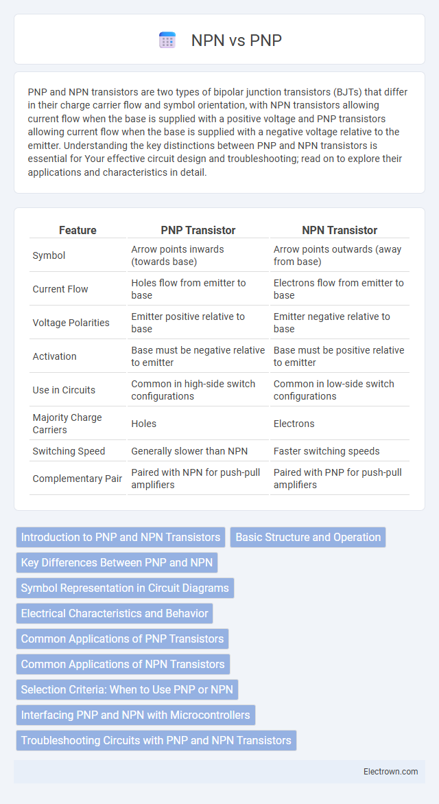
| Feature | PNP Transistor | NPN Transistor |
|---|---|---|
| Symbol | Arrow points inwards (towards base) | Arrow points outwards (away from base) |
| Current Flow | Holes flow from emitter to base | Electrons flow from emitter to base |
| Voltage Polarities | Emitter positive relative to base | Emitter negative relative to base |
| Activation | Base must be negative relative to emitter | Base must be positive relative to emitter |
| Use in Circuits | Common in high-side switch configurations | Common in low-side switch configurations |
| Majority Charge Carriers | Holes | Electrons |
| Switching Speed | Generally slower than NPN | Faster switching speeds |
| Complementary Pair | Paired with NPN for push-pull amplifiers | Paired with PNP for push-pull amplifiers |
Introduction to PNP and NPN Transistors
PNP and NPN transistors are bipolar junction transistors (BJTs) used to amplify or switch electronic signals. The PNP transistor has a layer of N-doped semiconductor between two P-type layers, while the NPN transistor consists of a P-doped layer between two N-type layers, influencing current flow direction and biasing conditions. Understanding the structure and operation of PNP and NPN transistors is essential for designing circuits in amplification and switching applications.
Basic Structure and Operation
PNP and NPN transistors differ in their basic structure, where PNP consists of a layer of N-type semiconductor sandwiched between two P-type layers, while NPN has a P-type layer between two N-type layers. In operation, PNP transistors conduct current when a small current flows out of the base, enabling hole flow from the emitter to the collector, whereas NPN transistors allow current to flow into the base, facilitating electron flow from the emitter to the collector. The polarity of voltage and current direction in circuits using PNP and NPN transistors determines their switching and amplification behavior.
Key Differences Between PNP and NPN
PNP and NPN transistors differ primarily in polarity and current flow direction: NPN transistors use electrons as majority carriers and allow current to flow when the base is high relative to the emitter, while PNP transistors use holes and conduct when the base is low relative to the emitter. Voltage supply connections are also opposite, with NPN typically connected to positive voltage rails and PNP to negative or ground. The switching and amplification behavior varies accordingly, impacting circuit design and application in analog and digital electronics.
Symbol Representation in Circuit Diagrams
PNP and NPN transistors are differentiated by their symbol representation in circuit diagrams, where the arrow direction on the emitter leg indicates current flow; the arrow points inward for PNP and outward for NPN transistors. This visual distinction aids engineers in identifying transistor types for correct biasing and circuit function. Accurate symbol interpretation ensures proper integration of PNP and NPN transistors in amplification and switching applications.
Electrical Characteristics and Behavior
PNP and NPN transistors differ primarily in their current flow and voltage polarity; NPN transistors conduct when a positive voltage is applied to the base relative to the emitter, allowing current to flow from collector to emitter, while PNP transistors conduct with a negative voltage at the base, enabling current flow from emitter to collector. NPN devices are typically preferred for switching and amplification in positive voltage circuits due to their faster electron mobility, whereas PNP types are used in negative voltage or complementary configurations. Understanding these electrical characteristics and behavior helps optimize your circuit design for efficiency and performance.
Common Applications of PNP Transistors
PNP transistors are commonly used in low-side switching applications where the load is connected to the positive voltage supply, such as in relay drivers, LED drivers, and audio amplifiers. Their design allows currents to flow from the emitter to the collector, making them suitable for switching and amplification tasks where the control signal is referenced to ground. Understanding the specific characteristics of PNP transistors can help you choose the right component for efficient circuit design.
Common Applications of NPN Transistors
NPN transistors are widely used in switching and amplification applications due to their ability to handle higher current flow with electron majority carriers. They serve as essential components in digital circuits, motor controllers, and audio amplifiers because of their fast switching speeds and high gain. Their prevalence in low-side switching configurations makes them ideal for grounding loads in power management systems.
Selection Criteria: When to Use PNP or NPN
PNP transistors are ideal for low-side switching where the load is connected to the ground, while NPN transistors suit high-side switching applications with the load connected to the positive voltage supply. Selecting between PNP and NPN depends on the required current flow direction and the control voltage level relative to the transistor's emitter. For circuits needing positive control signals referenced to ground, NPN transistors provide better switching performance and easier interfacing.
Interfacing PNP and NPN with Microcontrollers
Interfacing PNP and NPN transistors with microcontrollers requires understanding their switching behavior: NPN transistors switch on when the microcontroller outputs a high signal, while PNP transistors switch on when the microcontroller outputs a low signal. Proper resistor selection and wiring ensure safe current flow and prevent damage to your microcontroller pins during switching operations. Using level shifting and grounding techniques optimizes compatibility and signal integrity between the transistors and the microcontroller, enhancing overall circuit performance.
Troubleshooting Circuits with PNP and NPN Transistors
Troubleshooting circuits with PNP and NPN transistors requires understanding their polarity and current flow differences to identify faults accurately. NPN transistors conduct when a positive voltage is applied to the base relative to the emitter, while PNP transistors conduct when the base is more negative than the emitter, making polarity checks crucial. Your ability to use a multimeter to verify base-emitter voltages and transistor orientation improves the precision of diagnosing and repairing circuit failures.
PNP vs NPN Infographic