LVS (Layout Versus Schematic) and DRC (Design Rule Check) are critical verification steps in IC design to ensure your layout matches the schematic and complies with fabrication constraints. Explore the rest of the article to understand how LVS and DRC work together to prevent costly design errors.
Table of Comparison
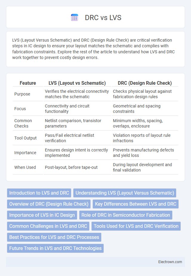
| Feature | LVS (Layout vs Schematic) | DRC (Design Rule Check) |
|---|---|---|
| Purpose | Verifies the electrical connectivity matches the schematic | Checks physical layout against fabrication design rules |
| Focus | Connectivity and circuit functionality | Geometrical and spacing constraints |
| Common Checks | Netlist comparison, transistor parameters | Minimum widths, spacing, overlaps, enclosure |
| Tool Output | Pass/Fail electrical netlist verification | Violation reports of layout rule infractions |
| Importance | Ensures design intent is correctly implemented | Prevents manufacturing defects and yield loss |
| When Used | Post-layout, before tape-out | During layout development and final validation |
Introduction to LVS and DRC
Layout Versus Schematic (LVS) and Design Rule Checking (DRC) are essential verification processes in integrated circuit design. LVS ensures your physical layout matches the intended schematic by comparing circuit connectivity, while DRC checks compliance with fabrication-specific geometric rules to prevent manufacturing defects. These steps guarantee accuracy and manufacturability of semiconductor devices.
Understanding LVS (Layout Versus Schematic)
LVS (Layout Versus Schematic) is a critical verification process in IC design that compares the physical layout of a chip with its schematic to ensure accuracy and consistency. This check identifies discrepancies such as missing components, incorrect connections, or mismatched device sizes that could lead to functional failures. Your design integrity relies heavily on LVS to validate that the layout correctly implements the intended circuit schematic before fabrication.
Overview of DRC (Design Rule Check)
Design Rule Check (DRC) ensures your integrated circuit layout adheres to manufacturing constraints by validating geometric and connectivity rules. It identifies violations such as spacing, width, and enclosure errors that could cause fabrication defects or yield issues. Performing DRC early in the design process minimizes costly revisions and enhances overall chip reliability.
Key Differences Between LVS and DRC
LVS (Layout Versus Schematic) verifies the consistency between the circuit layout and its corresponding schematic, ensuring that the physical design matches the intended electrical connectivity. DRC (Design Rule Check) focuses on checking the layout against manufacturing constraints, such as spacing, width, and layer configurations, to ensure manufacturability and reliability. Your design process benefits from using LVS to confirm functional correctness and DRC to validate adherence to fabrication rules, both essential for successful chip production.
Importance of LVS in IC Design
Layout Versus Schematic (LVS) is crucial in IC design for verifying that the physical layout matches the original circuit schematic, ensuring functional accuracy. Unlike Design Rule Check (DRC), which validates geometrical and manufacturing constraints, LVS ensures logical correctness by comparing connectivity and device parameters. Accurate LVS verification prevents costly design iterations and enhances overall chip reliability.
Role of DRC in Semiconductor Fabrication
Design Rule Checking (DRC) ensures semiconductor layouts comply with fabrication process constraints by verifying geometric and connectivity rules. It prevents manufacturing defects by detecting violations related to spacing, width, and layer alignment before mask production. DRC is crucial for maintaining yield and reliability in advanced semiconductor fabrication processes.
Common Challenges in LVS and DRC
Common challenges in Layout Versus Schematic (LVS) and Design Rule Checking (DRC) include managing complex design rule sets and ensuring accurate pattern recognition in intricate semiconductor geometries. Both processes often face difficulties in handling dense layouts and identifying subtle mismatches or violations that can lead to manufacturing defects. Your ability to optimize verification flows and update rulesets dynamically plays a crucial role in overcoming false positives and streamlining the overall design validation.
Tools Used for LVS and DRC Verification
LVS (Layout Versus Schematic) verification commonly utilizes tools such as Cadence Virtuoso Assura, Mentor Graphics Calibre, and Synopsys IC Validator to compare the drawn layout against the original schematic for electrical correctness. DRC (Design Rule Check) verification relies on similar platforms, including Mentor Graphics Calibre, Cadence Pegasus, and Synopsys IC Validator, to ensure the physical layout adheres to foundry-specific manufacturing constraints. Your design flow benefits from integrating these versatile tools, as they provide robust error detection and correction capabilities essential for successful IC fabrication.
Best Practices for LVS and DRC Processes
Executing Layout versus Schematic (LVS) and Design Rule Check (DRC) processes demands meticulous adherence to best practices, such as maintaining consistent naming conventions and ensuring complete and accurate netlist extraction. Your design must be segmented into modular blocks for more efficient verification and to facilitate pinpointing errors quickly. Utilizing up-to-date rule decks and comprehensive design guidelines from foundries enhances LVS and DRC accuracy, minimizing costly re-spins in chip development.
Future Trends in LVS and DRC Technologies
Future trends in Layout Versus Schematic (LVS) and Design Rule Checking (DRC) technologies emphasize enhanced automation powered by artificial intelligence and machine learning, significantly improving error detection accuracy and speed. Integration of cloud-based computing resources allows scalable parallel processing, reducing turnaround times for complex semiconductor designs. Emerging standards in design verification coupled with real-time feedback loops enable adaptive correction mechanisms, streamlining the overall verification workflow for advanced nodes.
LVS vs DRC Infographic