Pull-up resistors connect a signal line to a high voltage level to ensure a default "high" state, while pull-down resistors connect the line to ground to ensure a default "low" state, preventing undefined or floating inputs in digital circuits. Understanding their differences helps you design more reliable electronic systems; explore the rest of the article to learn when and how to use each resistor type effectively.
Table of Comparison
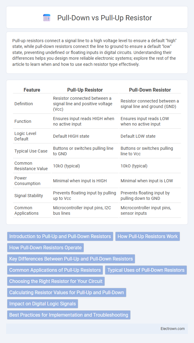
| Feature | Pull-Up Resistor | Pull-Down Resistor |
|---|---|---|
| Definition | Resistor connected between a signal line and positive voltage (Vcc) | Resistor connected between a signal line and ground (GND) |
| Function | Ensures input reads HIGH when no active input | Ensures input reads LOW when no active input |
| Logic Level Default | Default HIGH state | Default LOW state |
| Typical Use Case | Buttons or switches pulling line to GND | Buttons or switches pulling line to Vcc |
| Common Resistance Value | 10kO (typical) | 10kO (typical) |
| Power Consumption | Minimal when input is HIGH | Minimal when input is LOW |
| Signal Stability | Prevents floating input by pulling up to Vcc | Prevents floating input by pulling down to GND |
| Common Applications | Microcontroller input pins, I2C bus lines | Microcontroller input pins, sensor inputs |
Introduction to Pull-Up and Pull-Down Resistors
Pull-up and pull-down resistors are essential components used in digital circuits to ensure a defined logic level for input pins by connecting them to a high voltage (pull-up) or ground (pull-down). These resistors prevent floating inputs, which can cause unpredictable behavior or false triggering in microcontrollers and other digital devices. Understanding the function and placement of pull-up and pull-down resistors is crucial for stabilizing your circuit's performance and reliability.
How Pull-Up Resistors Work
Pull-up resistors connect the input pin of a digital circuit to a high voltage level, usually Vcc, ensuring the pin reads a definite logic HIGH when no active device drives the line. This resistor prevents the input from floating and picking up noise, which could cause unpredictable behavior in your circuit. By creating a stable voltage reference, pull-up resistors guarantee reliable signal readings essential for microcontroller inputs and communication lines.
How Pull-Down Resistors Operate
Pull-down resistors operate by connecting the input pin of a digital circuit to the ground (0V), ensuring the input reads a definite low logic level when no active voltage is applied. This prevents floating inputs and unpredictable behavior by providing a default reference voltage. Pull-down resistors typically have a high resistance value, such as 10k ohms, to limit current draw while maintaining a stable LOW input state.
Key Differences Between Pull-Up and Pull-Down Resistors
Pull-up resistors connect a signal line to a positive voltage supply (typically 5V or 3.3V) to ensure the input reads a high logic level when no active device is driving the line, while pull-down resistors connect the line to ground (0V) to guarantee a low logic level in the absence of input. The choice between pull-up and pull-down resistors depends on the desired default logic state and the type of input device, with pull-ups commonly used in open-drain or open-collector configurations. Pull-up resistors typically have values ranging from 1kO to 10kO, balancing power consumption and noise immunity, whereas pull-down resistors follow similar value ranges but ensure the input remains low when idle.
Common Applications of Pull-Up Resistors
Pull-up resistors are commonly used in digital circuits to ensure a defined logic level when switches or inputs are open or inactive, preventing floating states that cause unpredictable behavior. They are frequently found in microcontroller input pins, I2C communication lines, and button interfaces, providing a stable high voltage level by connecting the input to the positive supply voltage. Your circuit benefits from pull-up resistors by maintaining reliable and consistent signal readings during user interactions or data transmission.
Typical Uses of Pull-Down Resistors
Pull-down resistors are commonly used in digital circuits to ensure input pins read a defined logic low level when no active signal is present, preventing floating inputs that can cause erratic behavior. They are essential in switches, push-button interfaces, and microcontroller inputs to stabilize the input state during idle conditions. Typical values for pull-down resistors range from 10 kO to 100 kO, balancing power consumption and noise immunity.
Choosing the Right Resistor for Your Circuit
Selecting the right pull-up or pull-down resistor depends on your circuit's voltage levels and input characteristics. Pull-up resistors connect inputs to a positive voltage, ensuring a default HIGH state, while pull-down resistors connect inputs to ground, ensuring a default LOW state. Consider resistor value to balance power consumption and signal stability, typically ranging between 4.7kO and 10kO for most digital circuits.
Calculating Resistor Values for Pull-Up and Pull-Down
Calculating resistor values for pull-up and pull-down configurations involves balancing current consumption and signal integrity, typically using Ohm's Law (R = V/I). For a 5V supply, common resistor values range from 4.7kO to 10kO, ensuring a strong logic level without excessive power drain. Your choice depends on factors like input leakage current, switching speed, and noise immunity to maintain stable digital input signals.
Impact on Digital Logic Signals
Pull-up and pull-down resistors significantly influence digital logic signals by defining default voltage levels and preventing floating states that cause unpredictable behavior. A pull-up resistor connects the signal line to a high voltage (logic 1), while a pull-down resistor ties it to ground (logic 0), stabilizing input readings in microcontroller circuits. Choosing the appropriate resistor type ensures your digital inputs maintain consistent states, reducing noise and improving signal reliability.
Best Practices for Implementation and Troubleshooting
Pull-up and pull-down resistors stabilize input signals by ensuring defined voltage levels; best practices include selecting resistor values between 4.7kO and 10kO to balance power consumption and noise immunity. During implementation, verify proper connection to the power rail or ground, and confirm the resistor does not interfere with the signal's logic threshold. Troubleshooting involves checking for floating inputs, verifying continuity with a multimeter, and ensuring no conflicting pull resistors cause voltage contention or erratic behavior.
Pull-Up vs Pull-Down Resistor Infographic