A snubber circuit protects electronic components by limiting voltage spikes and absorbing transient energy, while a clamper circuit shifts voltage levels to prevent signals from going below or above a certain reference point. Explore the rest of the article to understand how your electronic designs can benefit from these essential circuits.
Table of Comparison
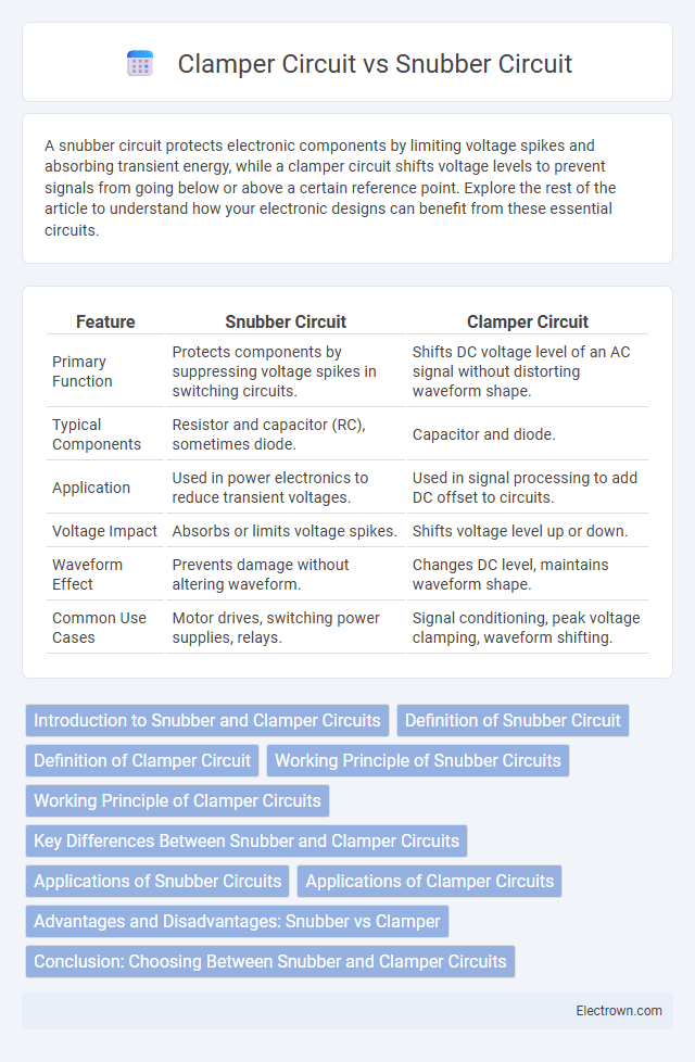
| Feature | Snubber Circuit | Clamper Circuit |
|---|---|---|
| Primary Function | Protects components by suppressing voltage spikes in switching circuits. | Shifts DC voltage level of an AC signal without distorting waveform shape. |
| Typical Components | Resistor and capacitor (RC), sometimes diode. | Capacitor and diode. |
| Application | Used in power electronics to reduce transient voltages. | Used in signal processing to add DC offset to circuits. |
| Voltage Impact | Absorbs or limits voltage spikes. | Shifts voltage level up or down. |
| Waveform Effect | Prevents damage without altering waveform. | Changes DC level, maintains waveform shape. |
| Common Use Cases | Motor drives, switching power supplies, relays. | Signal conditioning, peak voltage clamping, waveform shifting. |
Introduction to Snubber and Clamper Circuits
Snubber circuits protect electronic components by suppressing voltage spikes and limiting transient voltages, commonly used in power electronics and switching devices. Clamper circuits shift the voltage level of a waveform without altering its shape, often employed in signal conditioning and waveform restoration. Both circuits enhance circuit reliability and performance by managing voltage stress in different ways.
Definition of Snubber Circuit
A snubber circuit is an electrical device designed to suppress voltage spikes caused by the rapid switching of inductive loads, protecting components from transient overvoltages. Typically composed of resistors and capacitors, snubber circuits absorb and dissipate energy, reducing switching noise and electromagnetic interference. Unlike clamper circuits that shift voltage levels, snubbers primarily prevent damage and improve the reliability of power electronics.
Definition of Clamper Circuit
A clamper circuit is an electronic circuit that shifts the voltage level of a waveform by adding a DC level without altering its shape, typically composed of a diode, resistor, and capacitor. Unlike a snubber circuit, which suppresses voltage spikes to protect components, a clamper circuit restores or adjusts signal voltage levels in applications like signal processing and communication systems. You can use clamper circuits to prevent signal distortion by maintaining voltage within desired limits.
Working Principle of Snubber Circuits
Snubber circuits work by absorbing voltage spikes and limiting the rate of voltage change (dv/dt) across switching devices, protecting them from transient overvoltages. They typically consist of resistors and capacitors connected parallel to the load or switch, which dissipate and smooth sudden voltage surges caused by inductive loads. Your electronic systems benefit from snubber circuits by enhancing device reliability and reducing electromagnetic interference during switching operations.
Working Principle of Clamper Circuits
Clamper circuits work by shifting the entire waveform vertically to add a DC level to the AC input signal, effectively changing its baseline voltage without altering the shape. They utilize a capacitor and diode arrangement to temporarily store and release charge, allowing the output waveform to "clamp" above or below the zero-voltage line. This operation is essential in restoring signals that have been clipped or in protecting circuits by maintaining voltage levels within specified limits.
Key Differences Between Snubber and Clamper Circuits
Snubber circuits protect electronic components by absorbing voltage spikes and limiting transient voltages, primarily using resistors and capacitors to dissipate energy and prevent damage. Clamper circuits shift the voltage level of a waveform without changing its shape, using diodes and capacitors to add a DC level to the input signal. The key difference lies in function: snubbers mitigate transient voltage and protect circuits, while clampers modify signal voltage levels to maintain desired waveform positioning.
Applications of Snubber Circuits
Snubber circuits protect power semiconductor devices such as thyristors, transistors, and diodes from voltage spikes and transient voltage by absorbing excess energy in switching operations. They are widely applied in motor drives, switch-mode power supplies, and inverter circuits to enhance reliability and reduce electromagnetic interference. Their ability to suppress voltage overshoot and ringing improves the longevity and performance of electronic switching components.
Applications of Clamper Circuits
Clamper circuits are primarily used to shift the DC level of an input signal without altering its shape, making them essential in waveform restoration and signal processing applications. They find extensive use in television receivers for restoring the black level, in communication systems for adjusting signal baseline levels, and in analog-to-digital conversion to prevent negative signal voltages. Unlike snubber circuits that protect circuits from voltage spikes, clamper circuits focus on voltage level adjustment to maintain signal integrity.
Advantages and Disadvantages: Snubber vs Clamper
Snubber circuits protect semiconductor devices from voltage spikes by absorbing transient energy, offering advantages like improved reliability and reduced electromagnetic interference, but they can increase circuit complexity and power loss. Clamper circuits shift voltage levels to prevent negative swings, are simpler to implement, and consume less power, yet provide limited protection against high-frequency transients and may introduce DC offset in the output signal. The choice between snubber and clamper circuits depends on specific application requirements, such as transient suppression effectiveness versus circuit simplicity and power efficiency.
Conclusion: Choosing Between Snubber and Clamper Circuits
Snubber circuits are ideal for protecting semiconductor devices from voltage spikes and dissipating transient energy in switching applications, while clamper circuits are designed to shift the voltage level of a waveform without distortion. Selecting between snubber and clamper circuits depends on the primary requirement: transient voltage suppression favors snubbers, whereas voltage level adjustment favors clampers. Understanding the specific electrical environment and application ensures optimal circuit performance and device protection.
snubber circuit vs clamper circuit Infographic