A source follower offers high input impedance and low output impedance, making it ideal for impedance matching, while a common source amplifier provides high voltage gain but with moderate input and output impedances. Explore this article to understand which configuration best suits your amplification needs and how to optimize your circuit design.
Table of Comparison
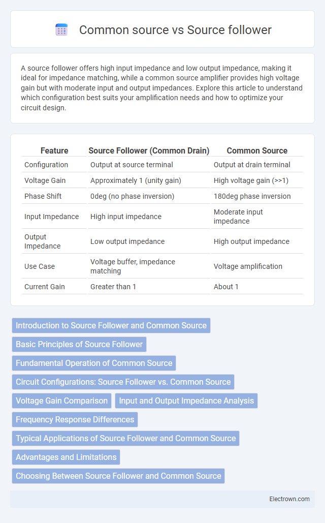
| Feature | Source Follower (Common Drain) | Common Source |
|---|---|---|
| Configuration | Output at source terminal | Output at drain terminal |
| Voltage Gain | Approximately 1 (unity gain) | High voltage gain (>>1) |
| Phase Shift | 0deg (no phase inversion) | 180deg phase inversion |
| Input Impedance | High input impedance | Moderate input impedance |
| Output Impedance | Low output impedance | High output impedance |
| Use Case | Voltage buffer, impedance matching | Voltage amplification |
| Current Gain | Greater than 1 | About 1 |
Introduction to Source Follower and Common Source
Source follower and common source are fundamental MOSFET amplifier configurations used in analog circuit design. The source follower, also known as a common drain amplifier, provides a high input impedance and voltage gain close to unity, making it ideal for impedance buffering applications. The common source configuration offers significant voltage gain with moderate input impedance, widely utilized in signal amplification stages requiring voltage gain.
Basic Principles of Source Follower
The source follower, also known as a common drain amplifier, operates by using the MOSFET's source terminal as the output, providing a voltage gain close to unity with high input impedance and low output impedance. It maintains the input voltage level while delivering current gain, making it ideal for buffering signals without significant voltage amplification. Understanding the basic principles of the source follower helps you design circuits that require impedance matching and signal isolation, distinguishing it Clearly from the common source configuration that provides voltage gain but has higher output impedance.
Fundamental Operation of Common Source
The fundamental operation of a common source amplifier involves converting an input voltage signal at the gate into an amplified output current at the drain, producing a voltage gain with a 180-degree phase shift. This stage utilizes the transistor's transconductance, where small changes in gate voltage modulate the drain current flowing through a load resistor, resulting in voltage amplification. You can achieve high voltage gain but relatively higher output impedance compared to the source follower configuration.
Circuit Configurations: Source Follower vs. Common Source
The source follower configuration, also known as the common drain amplifier, features the output taken from the source terminal, providing unity gain with high input impedance and low output impedance, ideal for impedance buffering. In contrast, the common source amplifier takes the output from the drain terminal, offering high voltage gain but with moderate input and output impedance, suitable for voltage amplification tasks. Your choice between these configurations depends on the desired gain and impedance characteristics in your circuit design.
Voltage Gain Comparison
Voltage gain in a source follower is typically slightly less than unity, providing a gain close to 1 while offering high input impedance and low output impedance. In contrast, a common source amplifier delivers significant voltage gain, often much greater than 1, due to the transistor's transconductance and load resistance. Your choice between the two depends on whether voltage gain or impedance buffering is the priority in your circuit design.
Input and Output Impedance Analysis
The source follower, or common drain amplifier, features high input impedance due to the gate terminal and low output impedance at the source, enabling efficient buffering with minimal signal loss. In contrast, the common source amplifier exhibits moderate input impedance and high output impedance, suitable for voltage amplification but less effective for driving low-impedance loads. Understanding these impedance characteristics is crucial for selecting the appropriate configuration in analog circuit design, especially in impedance matching and signal integrity applications.
Frequency Response Differences
Source follower configurations exhibit higher bandwidth and faster frequency response due to lower output impedance compared to common source amplifiers, which have higher gain but reduced bandwidth because of the Miller effect. The common source topology introduces a significant input capacitance that limits high-frequency performance, whereas the source follower's unity gain architecture minimizes capacitance impact, enabling superior high-frequency stability. Practical designs leverage source followers for buffering high-speed signals, while common source stages are preferred for voltage amplification at moderate frequencies.
Typical Applications of Source Follower and Common Source
Source followers are typically used in voltage buffering and impedance matching applications due to their high input impedance and low output impedance, ensuring signal integrity in analog circuits. Common source amplifiers excel in voltage amplification and are frequently utilized in sensor interfaces, RF amplifiers, and audio applications where gain and signal inversion are crucial. Understanding your circuit's requirements helps determine whether the low distortion of source followers or the high gain of common source stages best suits your design.
Advantages and Limitations
The source follower offers high input impedance and low output impedance, making it ideal for impedance matching and buffering applications, whereas the common source provides higher voltage gain suitable for amplification purposes. Source followers have limited voltage gain, typically less than unity, while common source amplifiers can achieve significant gain but suffer from lower input impedance and potential signal distortion. Your choice depends on whether you prioritize signal buffering with minimal loading or high-voltage amplification with gain constraints.
Choosing Between Source Follower and Common Source
When choosing between a source follower and common source configuration, consider voltage gain and input-output impedance requirements: source followers offer unity gain and high input impedance with low output impedance, making them ideal for impedance buffering. Common source amplifiers provide high voltage gain and moderate input impedance but have higher output impedance, suitable for signal amplification stages. Your application's need for signal integrity or voltage amplification determines which topology best optimizes performance.
Source follower vs Common source Infographic