Pull-up resistors connect a circuit node to a high voltage level ensuring a default "high" state, while pull-down resistors connect the node to ground, ensuring a default "low" state, both preventing floating inputs and false signals. Understanding the differences and applications of your pull-up and pull-down resistors is essential for designing reliable digital circuits, so explore the full article to learn more.
Table of Comparison
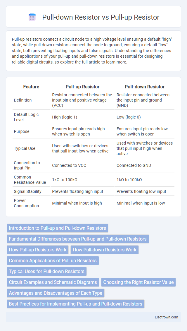
| Feature | Pull-up Resistor | Pull-down Resistor |
|---|---|---|
| Definition | Resistor connected between the input pin and positive voltage (VCC) | Resistor connected between the input pin and ground (GND) |
| Default Logic Level | High (logic 1) | Low (logic 0) |
| Purpose | Ensures input pin reads high when switch is open | Ensures input pin reads low when switch is open |
| Typical Use | Used with switches or devices that pull input low when active | Used with switches or devices that pull input high when active |
| Connection to Input Pin | Connected to VCC | Connected to GND |
| Common Resistance Value | 1kO to 100kO | 1kO to 100kO |
| Signal Stability | Prevents floating high input | Prevents floating low input |
| Power Consumption | Minimal when input is high | Minimal when input is low |
Introduction to Pull-up and Pull-down Resistors
Pull-up and pull-down resistors are essential components used in digital circuits to ensure a defined logic level on input pins. Pull-up resistors connect the input to a positive voltage (usually Vcc) ensuring a default HIGH state, while pull-down resistors connect the input to ground, establishing a default LOW state. These resistors prevent floating inputs and eliminate erratic behavior by providing a stable reference voltage.
Fundamental Differences between Pull-up and Pull-down Resistors
Pull-up resistors connect an input pin to a positive voltage source, ensuring the pin reads a high logic level when no active device is driving it, while pull-down resistors connect the pin to ground, securing a low logic level in the same condition. The fundamental difference lies in their default voltage states: pull-ups prevent floating high-impedance inputs by pulling the signal line to a known HIGH voltage, whereas pull-downs pull it to a known LOW voltage. Understanding these distinctions helps you design reliable digital circuits by properly controlling input signal biasing.
How Pull-up Resistors Work
Pull-up resistors connect an input pin to a positive voltage level, typically Vcc, ensuring the pin reads a high logic level when no other active device is driving it. This resistor prevents the input from floating, avoiding undefined or erratic behavior in digital circuits. You can rely on pull-up resistors to maintain stable logic signals by providing a default high state in microcontroller inputs or switch configurations.
How Pull-down Resistors Work
Pull-down resistors ensure a defined low logic level in digital circuits by connecting the input pin to ground through a resistor. This prevents the input from floating and picking up noise, which could cause erratic behavior. Your circuit maintains stability as the pull-down resistor provides a weak path to ground, allowing signals to override the low state when actively driven high.
Common Applications of Pull-up Resistors
Pull-up resistors are commonly used in digital circuits to ensure a known high logic level when a switch or input is open or disconnected, preventing floating inputs that can cause unpredictable behavior. In microcontroller interfaces, they stabilize input pins by connecting them to the supply voltage, enabling reliable reading of push-button states or sensor signals. You will often find pull-up resistors in I2C communication lines, where they maintain proper voltage levels for data and clock signals, ensuring accurate device communication.
Typical Uses for Pull-down Resistors
Pull-down resistors are typically used in digital circuits to ensure a defined logic level of zero (LOW) when no active device is driving the input, preventing floating states and erratic behavior. Common applications include stabilizing input pins on microcontrollers, ensuring switches or buttons read as LOW when open, and setting default states in programmable logic devices. These resistors pull the voltage to ground, providing reliable low-level signals critical for proper circuit operation and noise immunity.
Circuit Examples and Schematic Diagrams
Pull-up resistors connect an input pin to a positive voltage supply, ensuring the pin reads a high logic level when no active device drives it, commonly seen in button input circuits where pressing the button grounds the input. Pull-down resistors, in contrast, connect the pin to ground, forcing a low logic level in the absence of an input signal, often used in switches to activate a device when pressed. Your circuit schematic shows pull-up resistors connected to Vcc with the input node tied to a switch and pull-down resistors linked to ground, which helps prevent floating inputs and erratic behavior in digital circuits.
Choosing the Right Resistor Value
Selecting the correct resistor value for pull-up or pull-down resistors depends on balancing noise immunity and power consumption in your circuit. Typically, values between 4.7kO and 10kO are commonly used, providing a reliable logic level without excessive current draw. You should consider the input pin's leakage current and operating voltage to ensure the resistor maintains a stable logic state without impacting signal integrity.
Advantages and Disadvantages of Each Type
Pull-up resistors provide a reliable high logic level by default, minimizing noise susceptibility and preventing floating inputs, but can increase power consumption when the input is pulled low. Pull-down resistors ensure a default low logic level, which can be beneficial in specific circuit designs, yet they may cause erratic behavior if the input source is weak or disconnected. Choosing between pull-up and pull-down resistors depends on the desired default logic state, power consumption constraints, and the nature of the input signal.
Best Practices for Implementing Pull-up and Pull-down Resistors
When implementing pull-up and pull-down resistors, select resistor values between 4.7kO and 10kO to balance power consumption and signal integrity effectively. Ensure the chosen resistor maintains a defined logical level during idle states to prevent floating inputs, which can cause unpredictable behavior in microcontroller GPIO pins. Properly assess the circuit's voltage levels and logic requirements to decide between pull-up resistors, typically connected to Vcc, and pull-down resistors, typically connected to ground.
Pull-up Resistor vs Pull-down Resistor Infographic