Ball Grid Array (BGA) packages use solder balls to connect the chip to the PCB, offering excellent electrical performance and heat dissipation, while Land Grid Array (LGA) packages feature flat contact pads that rely on compression for connection, making them easier for rework and testing. Explore the rest of the article to understand which packaging type best suits your electronic design needs.
Table of Comparison
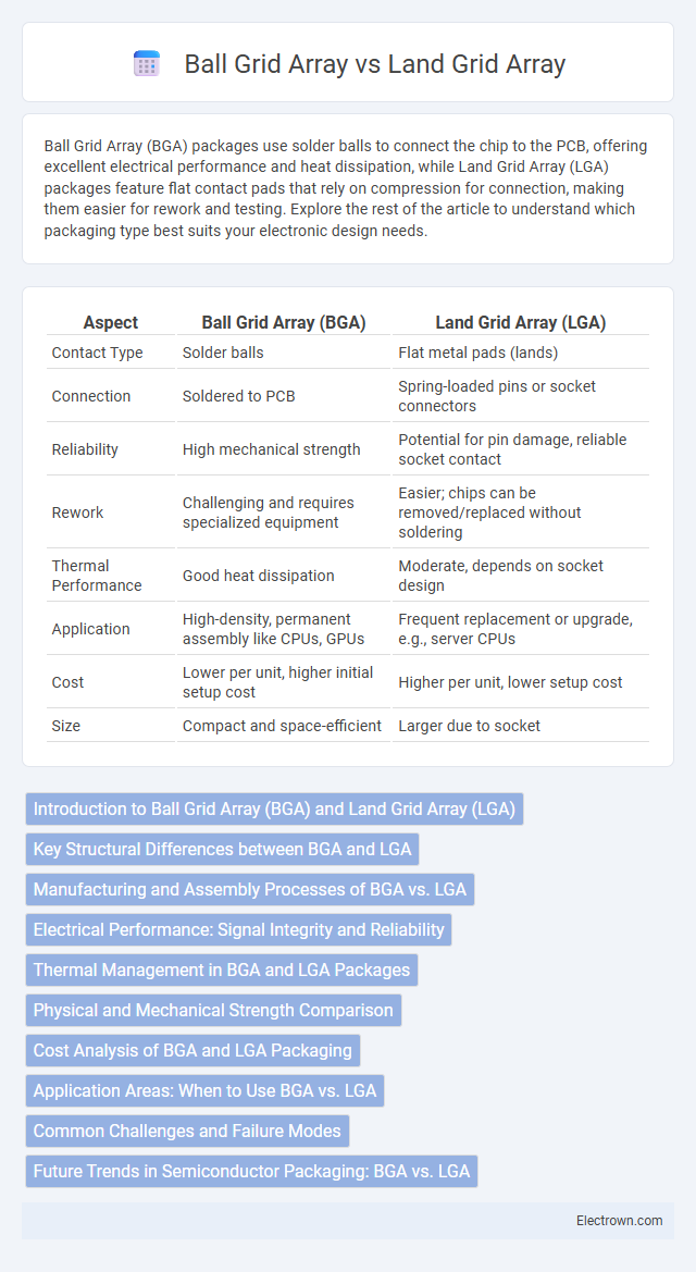
| Aspect | Ball Grid Array (BGA) | Land Grid Array (LGA) |
|---|---|---|
| Contact Type | Solder balls | Flat metal pads (lands) |
| Connection | Soldered to PCB | Spring-loaded pins or socket connectors |
| Reliability | High mechanical strength | Potential for pin damage, reliable socket contact |
| Rework | Challenging and requires specialized equipment | Easier; chips can be removed/replaced without soldering |
| Thermal Performance | Good heat dissipation | Moderate, depends on socket design |
| Application | High-density, permanent assembly like CPUs, GPUs | Frequent replacement or upgrade, e.g., server CPUs |
| Cost | Lower per unit, higher initial setup cost | Higher per unit, lower setup cost |
| Size | Compact and space-efficient | Larger due to socket |
Introduction to Ball Grid Array (BGA) and Land Grid Array (LGA)
Ball Grid Array (BGA) and Land Grid Array (LGA) are two types of surface-mount packaging technologies used for integrated circuits, distinguished by their connection methods to printed circuit boards (PCBs). BGA packages use tiny solder balls arranged in a grid on the underside, providing excellent electrical and thermal performance by creating a direct connection with the PCB during reflow soldering. LGA packages feature flat contact pads that align with corresponding pads on the PCB, relying on mechanical pressure rather than solder balls, commonly used in high-performance processors where reliable, low-profile connections are critical for your electronic device's functionality.
Key Structural Differences between BGA and LGA
Ball Grid Array (BGA) packages feature solder balls on the underside that connect directly to the PCB pads, providing strong mechanical bonds and excellent thermal performance. Land Grid Array (LGA) packages utilize flat contact pads instead of solder balls, requiring precise alignment and often a socket to maintain reliable electrical connections. Your choice between BGA and LGA depends on factors like assembly complexity, thermal management needs, and repairability.
Manufacturing and Assembly Processes of BGA vs. LGA
Ball Grid Array (BGA) packages utilize solder balls on the underside of the component that melt during reflow soldering to create electrical connections with the PCB pads, enabling reliable and high-density interconnects ideal for automated assembly. In contrast, Land Grid Array (LGA) packages feature flat contact pads that rely on pressure contacts or solder paste to establish connections, which requires precise alignment and can be more challenging during the assembly process. BGA manufacturing benefits from a self-aligning effect during reflow, improving yield rates, whereas LGA assembly demands strict mechanical fastening mechanisms to maintain consistent electrical contact and thermal performance.
Electrical Performance: Signal Integrity and Reliability
Ball Grid Array (BGA) offers superior electrical performance compared to Land Grid Array (LGA) due to its solder balls that provide consistent and low-resistance connections, enhancing signal integrity and reducing parasitic inductance. The solder joints in BGA improve thermal dissipation and mechanical reliability, which contributes to stable electrical performance over time. Your choice between BGA and LGA will impact signal integrity and device reliability based on the specific application requirements and environmental conditions.
Thermal Management in BGA and LGA Packages
Ball Grid Array (BGA) packages offer superior thermal management due to their direct solder ball connections that facilitate efficient heat dissipation through the PCB, enhancing performance in high-power applications. Land Grid Array (LGA) packages rely on flat contact pads, which may limit heat conduction and require additional thermal interface materials or heatsinks to manage temperature effectively. Optimizing thermal pathways in BGA designs reduces thermal resistance, leading to improved reliability and longevity compared to LGA packages.
Physical and Mechanical Strength Comparison
Ball Grid Array (BGA) packages offer superior mechanical strength due to their solder balls, which provide better shock absorption and enhanced stress distribution compared to Land Grid Array (LGA) packages that rely on flat contacts. BGAs typically exhibit improved physical robustness in harsh environments, reducing the risk of joint fatigue and solder cracking under mechanical stress. Your decision between BGA and LGA should consider these differences, especially for applications requiring high durability and long-term reliability.
Cost Analysis of BGA and LGA Packaging
Ball Grid Array (BGA) packaging generally incurs higher initial manufacturing costs due to complex solder ball attachment and precise reflow processes, but offers superior electrical performance and heat dissipation. Land Grid Array (LGA) provides cost advantages through simpler assembly and lower material expenses, making it favorable for applications prioritizing affordability and ease of repair. Your choice between BGA and LGA should consider total cost of ownership, factoring in production scale, reliability needs, and long-term maintenance expenses.
Application Areas: When to Use BGA vs. LGA
Ball Grid Array (BGA) is ideal for high-density, high-performance applications such as CPUs, graphics cards, and mobile devices due to its superior heat dissipation and electrical performance. Land Grid Array (LGA) is preferred in applications requiring a robust mechanical connection and easy socketing, commonly found in server processors and desktop CPUs. Your choice between BGA and LGA depends on factors like assembly complexity, thermal management, and the need for socketed vs. soldered connections.
Common Challenges and Failure Modes
Ball Grid Array (BGA) and Land Grid Array (LGA) packages both face common challenges such as solder joint fatigue caused by thermal cycling and mechanical stress during board flexing, leading to cracked or detached interconnections. Solder joint reliability is a critical failure mode in BGAs due to the spherical solder balls that can suffer from voids, insufficient wetting, or thermal expansion mismatches, while LGAs encounter contact resistance issues from oxidation or contamination on the land pads and pins. Both packaging types are susceptible to warpage during reflow soldering processes, which can result in incomplete connections or shorts affecting device performance.
Future Trends in Semiconductor Packaging: BGA vs. LGA
Ball Grid Array (BGA) and Land Grid Array (LGA) packaging continue to shape semiconductor innovation, with BGA excelling in high-density interconnects and thermal performance, accelerating adoption in advanced processors and GPUs. LGA gains traction for applications requiring higher pin counts and reliable mechanical connections, such as servers and telecommunications, driven by advancements in socket design and signal integrity. Emerging trends indicate a convergence where hybrid packaging integrates BGA's solder balls with LGA's contact pads, enabling enhanced scalability and miniaturization for next-generation devices.
Ball grid array vs Land grid array Infographic