GPIO output provides a clear high or low voltage signal suitable for driving many digital devices directly, while open drain allows multiple outputs to connect to a single line for wired-AND configurations, requiring an external pull-up resistor for proper operation. Understanding the differences between these output modes can help you choose the best configuration for your circuit; read on to explore their applications and advantages in detail.
Table of Comparison
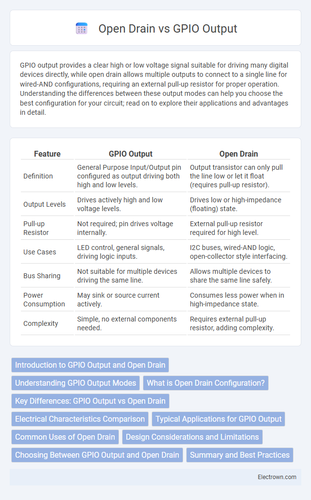
| Feature | GPIO Output | Open Drain |
|---|---|---|
| Definition | General Purpose Input/Output pin configured as output driving both high and low levels. | Output transistor can only pull the line low or let it float (requires pull-up resistor). |
| Output Levels | Drives actively high and low voltage levels. | Drives low or high-impedance (floating) state. |
| Pull-up Resistor | Not required; pin drives voltage internally. | External pull-up resistor required for high level. |
| Use Cases | LED control, general signals, driving logic inputs. | I2C buses, wired-AND logic, open-collector style interfacing. |
| Bus Sharing | Not suitable for multiple devices driving the same line. | Allows multiple devices to share the same line safely. |
| Power Consumption | May sink or source current actively. | Consumes less power when in high-impedance state. |
| Complexity | Simple, no external components needed. | Requires external pull-up resistor, adding complexity. |
Introduction to GPIO Output and Open Drain
GPIO output pins actively drive voltage levels high or low, providing a direct binary signal to connected devices. Open drain GPIO outputs can only pull the line low, requiring an external pull-up resistor to achieve a high state, enabling multiple devices to share a bus without interference. This configuration is critical in communication protocols like I2C, allowing safe, wired-AND logic operations on shared lines.
Understanding GPIO Output Modes
GPIO output modes include push-pull and open-drain configurations, each designed for specific applications in embedded systems. Push-pull mode actively drives the pin high or low, enabling faster switching and stronger signal integrity, while open-drain mode allows multiple devices to share a single line by only pulling it low, requiring an external pull-up resistor for a defined high state. Understanding the electrical characteristics and use cases of these modes is crucial for designing reliable digital interfaces and communication protocols.
What is Open Drain Configuration?
Open Drain configuration allows a GPIO pin to either pull the line to ground or leave it floating, relying on an external pull-up resistor to achieve a high state. This setup is ideal for wired-AND logic and enables multiple devices to share the same line without contention. Understanding Open Drain helps you design circuits with efficient bus communication and safe multi-device connections.
Key Differences: GPIO Output vs Open Drain
GPIO output pins actively drive the signal to both high and low states, providing a strong voltage level for precise control. Open drain outputs can only pull the line low, requiring an external pull-up resistor to achieve a high state, which allows multiple devices to share the same line without conflicts. Understanding this key difference helps optimize Your circuit design for power efficiency, signal integrity, and communication protocols like I2C.
Electrical Characteristics Comparison
GPIO output typically provides both sourcing and sinking current capabilities, enabling it to drive the pin high or low directly with a defined voltage level. Open drain outputs can only sink current, requiring an external pull-up resistor to achieve a high state, which leads to slower rise times and increased power consumption. Electrical characteristics differ as open drain offers flexibility for wired-AND configurations and level shifting, whereas GPIO output delivers faster switching and stronger drive strength for standard digital logic signals.
Typical Applications for GPIO Output
GPIO Output pins are commonly used for driving LEDs, controlling relays, and interfacing with digital logic circuits where a defined high or low voltage is required. They provide a strong push-pull drive capable of sourcing or sinking current, which is essential for powering components directly. Typical applications include microcontroller-to-peripheral communication, status indication, and simple on/off control in embedded systems.
Common Uses of Open Drain
Open Drain GPIO outputs are commonly used for wired-AND logic, bidirectional communication lines like I2C, and interfacing with devices operating at different voltage levels. They enable multiple devices to share a single line without conflict by allowing the line to be pulled low without driving it high directly. Your circuit benefits from Open Drain when you need safe multi-device communication or level shifting between components.
Design Considerations and Limitations
GPIO output modes impact signal integrity and device compatibility, with standard push-pull outputs providing both sourcing and sinking currents for faster switching, while open-drain configurations require external pull-up resistors, limiting speed but allowing multiple devices to share a line safely. Your design must consider power consumption, voltage levels, and the need for wired-AND logic when selecting open-drain to prevent bus contention and ensure reliable communication. Limitations of open-drain include slower rise times due to resistor-capacitor delays and increased susceptibility to noise, making it less suitable for high-speed or precision timing applications compared to push-pull outputs.
Choosing Between GPIO Output and Open Drain
Choosing between GPIO Output and Open Drain depends on the specific voltage levels and device compatibility in your circuit. GPIO Output provides a direct push-pull drive allowing high and low voltage states, ideal for standard digital signaling. Open Drain outputs can only sink current and require an external pull-up resistor, making them suitable for wired-AND configurations and applications involving multiple devices sharing a line.
Summary and Best Practices
GPIO output pins actively drive the line high or low, providing a strong and direct signal, while open-drain outputs only pull the line low, requiring an external pull-up resistor to achieve a high state. Best practices suggest using GPIO output mode when clear and fast switching is needed, whereas open-drain is ideal for wired-AND configurations, level shifting, or interfacing with different voltage domains. Your choice impacts signal integrity and power consumption, so select the mode based on specific application requirements and system design constraints.
GPIO Output vs Open Drain Infographic