Bipolar ADCs can measure both positive and negative input voltages, making them ideal for applications requiring AC signal conversion, while unipolar ADCs only measure positive voltages, suited for DC signals. Explore the rest of the article to understand which ADC type best fits your specific signal processing needs.
Table of Comparison
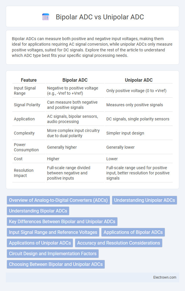
| Feature | Bipolar ADC | Unipolar ADC |
|---|---|---|
| Input Signal Range | Negative to positive voltage (e.g., -Vref to +Vref) | Only positive voltage (0 to +Vref) |
| Signal Polarity | Can measure both negative and positive signals | Measures only positive signals |
| Application | AC signals, bipolar sensors, audio processing | DC signals, single polarity sensors |
| Complexity | More complex input circuitry due to dual polarity | Simpler input design |
| Power Consumption | Generally higher | Generally lower |
| Cost | Higher | Lower |
| Resolution Impact | Full-scale range divided between negative and positive inputs | Full-scale range used for positive input, better resolution for positive signals |
Overview of Analog-to-Digital Converters (ADCs)
Analog-to-Digital Converters (ADCs) transform continuous analog signals into discrete digital values, crucial for digital processing. Bipolar ADCs convert input signals ranging from negative to positive voltages, typically covering spans like +-10V, enabling measurement of signals with positive and negative swings. Unipolar ADCs accept only non-negative input voltages, often from 0 to a positive full-scale voltage, making them ideal for applications where signals do not drop below zero.
Understanding Unipolar ADCs
Unipolar ADCs measure input signals ranging exclusively from 0 volts to a positive reference voltage, making them ideal for applications with only positive voltage levels such as sensor outputs or battery voltage monitoring. These converters typically offer simpler circuit design and improved resolution for low-voltage signals compared to bipolar ADCs, which handle both positive and negative inputs by centering around zero volts. Unipolar ADCs are preferred in precision digital measurement systems requiring high accuracy within the 0 to reference voltage range.
Understanding Bipolar ADCs
Bipolar ADCs can measure both positive and negative voltage signals, enabling accurate conversion of alternating input signals within a specific voltage range, typically +-Vref. This versatility contrasts with unipolar ADCs, which only process positive voltages from 0 to Vref, limiting their application in systems requiring accurate detection of signals that swing below zero volts. Understanding bipolar ADCs helps you select the proper conversion method for applications involving AC signals, audio processing, or sensor outputs with negative voltage components.
Key Differences Between Bipolar and Unipolar ADCs
Bipolar ADCs can convert both positive and negative input voltages, making them suitable for AC signals and applications requiring measurement around a zero baseline, whereas unipolar ADCs only process positive voltages from zero to a defined maximum. Bipolar ADCs often require a dual power supply and more complex input circuitry, while unipolar ADCs operate with a single power supply and simpler design. The selection between bipolar and unipolar ADCs depends on the signal range and application, with bipolar ADCs preferred for audio, sensor signals with negative components, and unipolar ADCs commonly used in DC voltage measurement and digital interfacing.
Input Signal Range and Reference Voltages
Bipolar ADCs handle input signals that range from negative to positive voltages, typically matching the reference voltage span that extends symmetrically around zero, such as +-V_ref. Unipolar ADCs, in contrast, convert only positive input signals, with input ranges from 0 to a positive reference voltage, often 0 to V_ref. Understanding your signal's voltage range and aligning it with the correct ADC type and reference voltage ensures accurate digital representation.
Applications of Bipolar ADCs
Bipolar ADCs are widely applied in audio signal processing and instrumentation systems where signals vary above and below zero volts, such as in electrocardiogram (ECG) monitoring and industrial control sensors. Their ability to accurately capture both positive and negative voltage swings makes them essential in communication systems and feedback control loops requiring precise bipolar input measurement. These converters are preferred in scientific research and medical devices where symmetrical signal acquisition is critical for data integrity.
Applications of Unipolar ADCs
Unipolar ADCs are widely used in applications where signals only have positive voltages, such as temperature sensing and light intensity measurements. These ADCs are preferred in battery-powered and low-voltage systems due to their simpler design and lower power consumption compared to bipolar ADCs. Common industries utilizing unipolar ADCs include environmental monitoring, consumer electronics, and industrial automation.
Accuracy and Resolution Considerations
Bipolar ADCs provide accurate measurement of signals that swing both positive and negative, enhancing the effective resolution for AC or bipolar signals compared to unipolar ADCs, which only measure positive voltages. Resolution in bipolar ADCs is often expressed across a larger voltage range, effectively doubling the input span for the same bit-depth, improving sensitivity to small changes around zero. Accuracy depends on factors like offset and gain error, where bipolar ADCs require precise zero-level calibration to maintain fidelity, while unipolar ADCs avoid negative offset complications but at the cost of limited voltage range.
Circuit Design and Implementation Factors
Bipolar ADCs require symmetric power supplies and more complex input stage design to handle both positive and negative voltage ranges, impacting circuit complexity and cost. Unipolar ADCs operate with a single supply voltage, simplifying input circuitry and reducing power consumption in implementation. The choice affects reference voltage configuration, input buffering requirements, and overall noise performance in the analog-to-digital conversion process.
Choosing Between Bipolar and Unipolar ADCs
Choosing between bipolar and unipolar ADCs depends on the input signal range and application requirements; bipolar ADCs measure signals spanning both positive and negative voltages, suitable for AC signals or bi-directional sensors. Unipolar ADCs handle only positive voltage ranges, ideal for applications with strictly positive signals like temperature sensors or light intensity measurements. Selecting the appropriate ADC type impacts accuracy, resolution, and system complexity, making it critical to match the device to the signal characteristics and expected voltage range.
bipolar ADC vs unipolar ADC Infographic