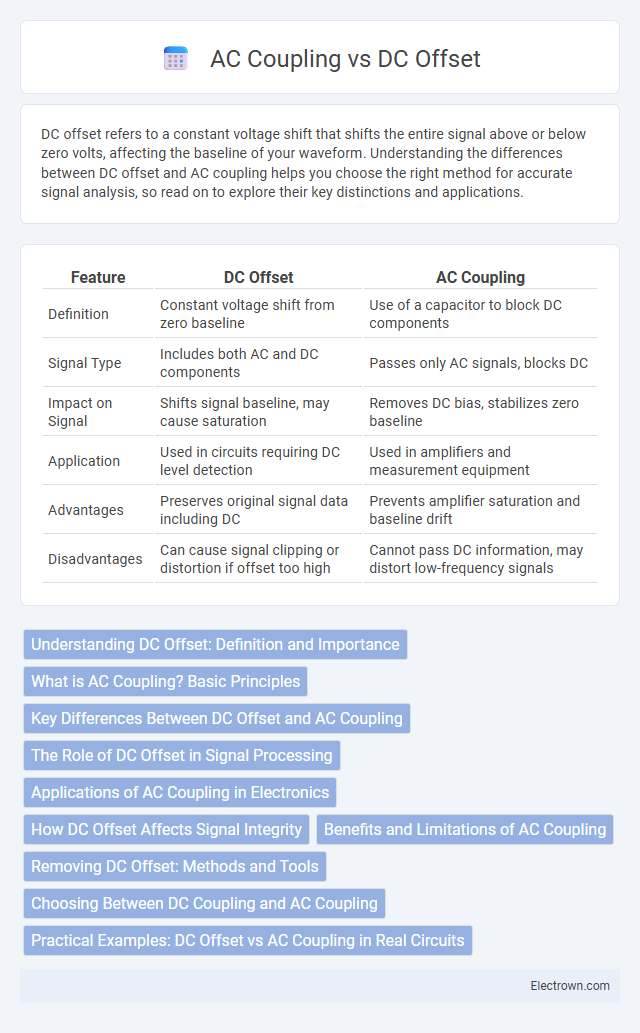
DC offset refers to a constant voltage shift that shifts the entire signal above or below zero volts, affecting the baseline of your waveform. Understanding the differences between DC offset and AC coupling helps you choose the right method for accurate signal analysis, so read on to explore their key distinctions and applications.
Table of Comparison
| Feature | DC Offset | AC Coupling |
|---|---|---|
| Definition | Constant voltage shift from zero baseline | Use of a capacitor to block DC components |
| Signal Type | Includes both AC and DC components | Passes only AC signals, blocks DC |
| Impact on Signal | Shifts signal baseline, may cause saturation | Removes DC bias, stabilizes zero baseline |
| Application | Used in circuits requiring DC level detection | Used in amplifiers and measurement equipment |
| Advantages | Preserves original signal data including DC | Prevents amplifier saturation and baseline drift |
| Disadvantages | Can cause signal clipping or distortion if offset too high | Cannot pass DC information, may distort low-frequency signals |
Understanding DC Offset: Definition and Importance
DC offset refers to a constant voltage shift in an electrical signal that can distort signal accuracy by shifting the baseline away from zero volts, impacting the performance of audio, communication, and measurement systems. Understanding and managing DC offset is crucial because it can cause erroneous readings, decreased dynamic range, and potential damage to electronic components. Accurate signal processing relies on effectively identifying and correcting DC offset to maintain signal integrity and system reliability.
What is AC Coupling? Basic Principles
AC coupling is a technique used in electronic signal processing that blocks direct current (DC) components while allowing alternating current (AC) signals to pass through. This is achieved by placing a capacitor in series with the signal path, which removes the DC offset by blocking steady voltage levels and only transmitting changes in voltage. The basic principle of AC coupling relies on the capacitor's ability to charge and discharge in response to varying signal voltages, thus isolating AC signals from any DC bias present in the input.
Key Differences Between DC Offset and AC Coupling
DC offset represents a constant voltage shift from zero, causing a signal baseline to shift, while AC coupling blocks this DC component to allow the alternating current variations to pass through. AC coupling is used in oscilloscopes and audio equipment to remove unwanted DC bias, ensuring accurate measurement of AC signals without distortion. Understanding the key differences helps you choose the right method to maintain signal integrity in your electronic measurements or designs.
The Role of DC Offset in Signal Processing
DC offset in signal processing represents a constant voltage shift from zero, affecting the accuracy and interpretation of waveforms in measurements and communications. AC coupling removes this offset by blocking the DC component, allowing only the varying AC signal to pass through, which is crucial in amplifiers and oscilloscopes to prevent saturation and distortion. Proper management of DC offset ensures signal integrity, reduces noise interference, and optimizes performance in analog and digital systems.
Applications of AC Coupling in Electronics
AC coupling is widely used in electronics to block DC components while allowing AC signals to pass, making it essential in audio equipment, oscilloscopes, and communication systems where signal integrity is critical. It prevents DC offset from saturating amplifiers or distorting measurements, ensuring accurate signal representation in mixed-frequency signals. In RF circuits and sensor interfaces, AC coupling stabilizes the baseline and enhances signal clarity by isolating the AC signal from unwanted DC bias.
How DC Offset Affects Signal Integrity
DC offset in electronic signals shifts the baseline voltage from zero, causing distortion that can lead to inaccurate signal representation and reduced dynamic range in analog-to-digital converters (ADCs). This shift introduces errors in signal processing circuits, potentially saturating amplifiers or causing clipping in downstream components, which degrades overall signal integrity. AC coupling removes the DC offset by blocking the DC component, preserving signal quality and ensuring accurate transmission and measurement of the desired AC signal components.
Benefits and Limitations of AC Coupling
AC coupling effectively blocks DC offset, allowing measurement of small AC signals superimposed on large DC voltages, which is crucial in applications like audio and signal processing. It enables cleaner signal analysis by preventing amplifier saturation and baseline shift but introduces limitations such as distortion of low-frequency components and inability to measure true DC levels. Careful consideration of cutoff frequency is essential to balance signal integrity and DC isolation in AC-coupled systems.
Removing DC Offset: Methods and Tools
Removing DC offset effectively enhances signal integrity in audio and measurement systems by eliminating unwanted baseline shifts. Common methods include employing high-pass filters, operational amplifier circuits with capacitor coupling, and digital signal processing algorithms that subtract mean voltage values. Your choice of tools, such as oscilloscopes with DC blocking capabilities or audio interfaces with built-in DC offset correction, plays a crucial role in achieving accurate, clear signal representation.
Choosing Between DC Coupling and AC Coupling
Choosing between DC coupling and AC coupling depends on the signal characteristics and measurement objectives: DC coupling preserves the entire signal including any DC offset, crucial for accurate voltage level analysis and power supply testing. AC coupling blocks DC components by adding a capacitor in series, ideal for isolating small AC signals superimposed on large DC offsets, such as audio or communication signals. Engineers prioritize DC coupling when monitoring steady-state voltages and AC coupling when eliminating low-frequency noise or drift to enhance signal clarity.
Practical Examples: DC Offset vs AC Coupling in Real Circuits
In audio amplifiers, DC offset can cause speaker damage by pushing the cone out of its neutral position, whereas AC coupling with capacitors blocks this offset, preserving sound quality. Oscilloscopes use AC coupling to remove DC components from signals, allowing clearer analysis of small AC variations on a large DC baseline. In sensor circuits, removing DC offset through AC coupling enhances measurement accuracy by preventing saturation and focusing on the dynamic signal changes.
DC Offset vs AC Coupling Infographic