Tapped delay lines provide precise time delays by distributing signals across multiple delay elements, making them ideal for high-frequency analog signal processing, while switched capacitor circuits use discrete capacitors and switches to simulate resistors, offering superior accuracy in integrated circuit filters and data converters. Explore the rest of the article to discover which technology best suits your specific application needs and how their unique characteristics impact circuit performance.
Table of Comparison
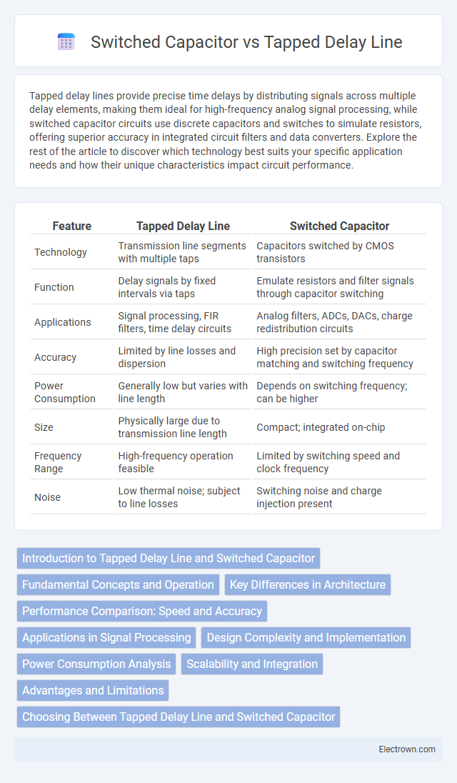
| Feature | Tapped Delay Line | Switched Capacitor |
|---|---|---|
| Technology | Transmission line segments with multiple taps | Capacitors switched by CMOS transistors |
| Function | Delay signals by fixed intervals via taps | Emulate resistors and filter signals through capacitor switching |
| Applications | Signal processing, FIR filters, time delay circuits | Analog filters, ADCs, DACs, charge redistribution circuits |
| Accuracy | Limited by line losses and dispersion | High precision set by capacitor matching and switching frequency |
| Power Consumption | Generally low but varies with line length | Depends on switching frequency; can be higher |
| Size | Physically large due to transmission line length | Compact; integrated on-chip |
| Frequency Range | High-frequency operation feasible | Limited by switching speed and clock frequency |
| Noise | Low thermal noise; subject to line losses | Switching noise and charge injection present |
Introduction to Tapped Delay Line and Switched Capacitor
Tapped Delay Line uses a series of delay elements to create multiple output taps at different time intervals, enabling precise timing control in signal processing applications. Switched Capacitor circuits replicate resistive behavior by rapidly switching capacitors in and out of the circuit, allowing accurate analog filtering and integration without using resistors. Your choice between these technologies depends on factors like desired signal accuracy, frequency range, and power consumption.
Fundamental Concepts and Operation
Tapped Delay Lines utilize a series of delay elements to create multiple time-shifted versions of an input signal, enabling temporal signal processing with precise timing intervals. Switched Capacitor circuits mimic resistor behavior by rapidly charging and discharging capacitors through switches, allowing accurate analog signal filtering and integration in integrated circuits. The fundamental operation of Tapped Delay Lines relies on signal propagation delay, whereas Switched Capacitor circuits operate based on discrete-time charge transfer controlled by clock signals.
Key Differences in Architecture
Tapped Delay Line architecture relies on a series of delay elements and taps to sample signal values at multiple time intervals, enabling precise time-domain processing. Switched Capacitor circuits use capacitors and switches controlled by clock signals to emulate resistive behavior and perform filtering in discrete time. The fundamental difference lies in the tapped delay line's continuous-time signal propagation versus the switched capacitor's discrete-time charge transfer mechanism.
Performance Comparison: Speed and Accuracy
Tapped Delay Lines provide high-speed signal processing with minimal latency, making them ideal for applications requiring rapid response times. Switched Capacitor circuits excel in accuracy due to precise charge quantization and mismatch compensation techniques, ensuring superior signal fidelity. You must weigh the speed advantage of tapped delay lines against the higher accuracy offered by switched capacitors based on your system's performance requirements.
Applications in Signal Processing
Tapped Delay Lines are widely used in digital signal processing for implementing finite impulse response (FIR) filters and equalizers, offering precise time delays essential for echo cancellation and radar signal analysis. Switched Capacitor circuits excel in analog signal processing applications such as modulators, filters, and data converters, providing accuracy without the need for precision resistors. Your choice between these technologies depends on whether the application demands digital delay precision or analog filtering versatility.
Design Complexity and Implementation
Tapped delay lines offer simpler design and straightforward implementation using passive components like inductors and capacitors, making them suitable for high-frequency analog signal processing. Switched capacitor circuits involve complex timing control and require precise clock generation, which increases design complexity and layout challenges in integrated systems. Your choice depends on whether ease of implementation or flexibility in adjustable delay is prioritized in the specific application.
Power Consumption Analysis
Tapped delay lines typically exhibit lower power consumption compared to switched capacitor circuits due to their passive nature and fewer active switching elements. Switched capacitor circuits consume more power because they rely heavily on clock-driven switches and operational amplifiers, which contribute to dynamic power dissipation. Power analysis shows tapped delay lines excel in low-power applications, particularly in high-frequency analog signal processing where minimal active components reduce overall energy usage.
Scalability and Integration
Tapped Delay Lines offer limited scalability due to their dependence on discrete components and physical layout constraints, making large-scale integration challenging. Switched Capacitor circuits excel in scalability and integration since they leverage standard CMOS processes, enabling compact, programmable designs suitable for complex, high-density systems. Your choice between them should consider the required integration level and system size, favoring switched capacitor techniques for scalable, integrated solutions.
Advantages and Limitations
Tapped delay lines offer high-speed signal processing with minimal power consumption, making them ideal for RF and microwave applications, but they are limited by physical size and fixed delay resolution. Switched capacitor circuits provide precise and tunable time delays with ease of integration in CMOS technology, enabling greater design flexibility; however, they suffer from higher power consumption and noise sensitivity. Both technologies balance trade-offs between delay accuracy, power efficiency, and scalability depending on specific application requirements.
Choosing Between Tapped Delay Line and Switched Capacitor
Choosing between tapped delay line and switched capacitor circuits depends on required delay accuracy, power consumption, and integration level. Tapped delay lines offer precise, high-frequency delays ideal for applications requiring low jitter and minimal signal distortion, while switched capacitor circuits provide flexible, programmable delay with better integration in CMOS technology. Engineers prioritize tapped delay lines for RF and high-speed digital applications, whereas switched capacitors are favored in analog signal processing and low-power environments.
Tapped Delay Line vs Switched Capacitor Infographic