Bipolar PWM switches the output voltage between positive and negative supply levels, creating a symmetrical waveform with higher harmonic content, while Unipolar PWM alternates the output between zero and positive or zero and negative supply, reducing electromagnetic interference and improving efficiency. Understand the key differences and applications of each modulation technique to optimize Your power electronics design by reading the rest of the article.
Table of Comparison
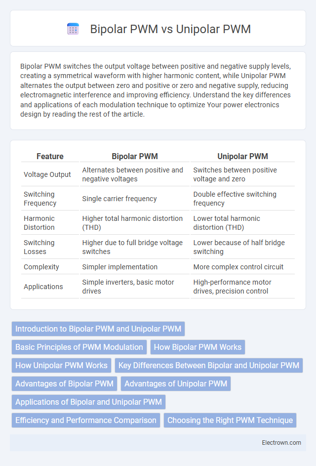
| Feature | Bipolar PWM | Unipolar PWM |
|---|---|---|
| Voltage Output | Alternates between positive and negative voltages | Switches between positive voltage and zero |
| Switching Frequency | Single carrier frequency | Double effective switching frequency |
| Harmonic Distortion | Higher total harmonic distortion (THD) | Lower total harmonic distortion (THD) |
| Switching Losses | Higher due to full bridge voltage switches | Lower because of half bridge switching |
| Complexity | Simpler implementation | More complex control circuit |
| Applications | Simple inverters, basic motor drives | High-performance motor drives, precision control |
Introduction to Bipolar PWM and Unipolar PWM
Bipolar PWM switches the output voltage between positive and negative DC supply levels, resulting in a waveform that alternates polarity, which enhances harmonic reduction and improves power quality in inverters. Unipolar PWM toggles the output voltage between zero and either positive or negative DC supply voltage, producing lower voltage stress on power devices and reduced electromagnetic interference. Both methods are extensively used in motor drives and power electronics, with selection depending on application-specific requirements for efficiency and waveform quality.
Basic Principles of PWM Modulation
Bipolar PWM modulation alternates the output voltage between positive and negative levels relative to zero, generating a waveform that switches directly between +Vdc and -Vdc. Unipolar PWM, by contrast, modulates the output between zero and either a positive or negative voltage, reducing switching frequency on each transistor and resulting in lower harmonic distortion. The fundamental principle of PWM involves controlling the duty cycle of switching signals to regulate output voltage and power by varying the width of pulses within a fixed period.
How Bipolar PWM Works
Bipolar PWM works by alternating the voltage polarity applied to the load, switching between positive and negative voltages relative to the neutral point. This method produces a waveform where the output voltage swings both above and below zero, resulting in a higher harmonic content but improved power efficiency compared to unipolar PWM. The switching frequency and duty cycle control the effective voltage and current supplied, making bipolar PWM suitable for driving AC motors and inverters.
How Unipolar PWM Works
Unipolar PWM operates by switching voltage between zero and positive or zero and negative voltages, effectively producing pulses on both the high and low sides of the waveform, which reduces harmonic distortion and switching losses compared to bipolar PWM. The output voltage alternates between zero and one polarity, improving efficiency and smoothing the output waveform. This approach enhances inverter performance by delivering finer control over voltage levels and minimizing electromagnetic interference in motor drives and power electronics.
Key Differences Between Bipolar and Unipolar PWM
Bipolar PWM switches the output voltage between positive and negative rails, producing a waveform that toggles symmetrically around zero, which results in higher harmonic distortion but better utilization of DC bus voltage. Unipolar PWM changes the output voltage between zero and positive or zero and negative rail, leading to lower harmonic distortion, reduced electromagnetic interference, and improved motor efficiency. The key differences lie in their switching patterns, harmonic content, and impact on power quality and device stress.
Advantages of Bipolar PWM
Bipolar PWM offers improved harmonic performance by producing a symmetrical voltage waveform that reduces common-mode noise and electromagnetic interference (EMI). It provides better utilization of the DC bus voltage, resulting in higher output voltage and torque in motor control applications. The simplicity of implementation and compatibility with existing inverter topologies further enhance its efficiency and reliability in power electronics systems.
Advantages of Unipolar PWM
Unipolar PWM offers improved efficiency and reduced harmonic distortion in inverter output compared to Bipolar PWM, resulting in smoother motor operation and lower electromagnetic interference. By switching only one power transistor at a time per switching cycle, Unipolar PWM reduces switching losses and thermal stress on components, extending device lifespan. This modulation technique also enables finer control of output voltage and frequency, enhancing performance in precision applications like variable-speed drives.
Applications of Bipolar and Unipolar PWM
Bipolar PWM is commonly used in applications requiring simple control and lower switching frequency, such as in basic AC motor drives and inverters for residential solar power systems. Unipolar PWM is preferred in high-performance applications like industrial motor drives and electric vehicle inverters due to its ability to reduce switching losses and electromagnetic interference. Both techniques optimize power efficiency and waveform quality depending on the specific demands of the application.
Efficiency and Performance Comparison
Bipolar PWM switches the output voltage between positive and negative rails, resulting in higher harmonic distortion but simpler implementation, while Unipolar PWM switches between positive and zero voltage, reducing switching losses and improving efficiency. Unipolar PWM typically offers better performance in terms of lower electromagnetic interference (EMI) and smoother output waveforms, enhancing overall motor control accuracy. Efficiency gains in Unipolar PWM arise from reduced voltage stress on power devices, making it more suitable for high-frequency and high-performance applications.
Choosing the Right PWM Technique
Choosing the right PWM technique depends on your application's efficiency and output voltage requirements, with Bipolar PWM offering simpler implementation and better power utilization through voltage swings between positive and negative rails. Unipolar PWM reduces switching losses by toggling output voltage between zero and positive or negative voltage, resulting in lower electromagnetic interference and smoother motor operation. Consider your system's complexity, thermal management, and noise sensitivity when selecting between Bipolar and Unipolar PWM for optimal performance.
Bipolar PWM vs Unipolar PWM Infographic