A crowbar circuit offers robust overvoltage protection by shorting the power supply output to ground, quickly triggering a fuse or breaker to protect sensitive components. Understanding the differences between crowbar and clamp circuits can help you choose the ideal method for safeguarding your electronic devices; explore the full article to learn more.
Table of Comparison
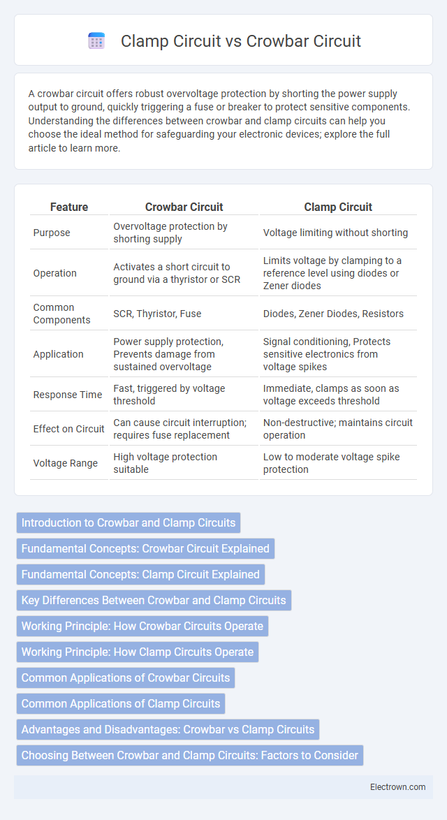
| Feature | Crowbar Circuit | Clamp Circuit |
|---|---|---|
| Purpose | Overvoltage protection by shorting supply | Voltage limiting without shorting |
| Operation | Activates a short circuit to ground via a thyristor or SCR | Limits voltage by clamping to a reference level using diodes or Zener diodes |
| Common Components | SCR, Thyristor, Fuse | Diodes, Zener Diodes, Resistors |
| Application | Power supply protection, Prevents damage from sustained overvoltage | Signal conditioning, Protects sensitive electronics from voltage spikes |
| Response Time | Fast, triggered by voltage threshold | Immediate, clamps as soon as voltage exceeds threshold |
| Effect on Circuit | Can cause circuit interruption; requires fuse replacement | Non-destructive; maintains circuit operation |
| Voltage Range | High voltage protection suitable | Low to moderate voltage spike protection |
Introduction to Crowbar and Clamp Circuits
Crowbar circuits protect sensitive electronic components by rapidly shorting the power supply line to ground when an overvoltage condition occurs, effectively preventing damage. Clamp circuits regulate voltage by diverting excess current through a voltage-dependent element like a Zener diode or transient voltage suppression diode, maintaining the voltage at a safe level. Both circuits are essential in power supply protection but function differently in their approach to controlling voltage spikes and surges.
Fundamental Concepts: Crowbar Circuit Explained
A crowbar circuit is designed to protect electronic devices by shorting the power supply line to ground when an overvoltage condition occurs, effectively creating a low-resistance path to prevent damage. Unlike clamp circuits that limit voltage by diverting excess current, crowbars trigger a deliberate short circuit using components like silicon-controlled rectifiers (SCRs) for rapid response. This fundamental operation makes crowbar circuits highly effective in safeguarding sensitive electronics from sudden voltage spikes.
Fundamental Concepts: Clamp Circuit Explained
A clamp circuit is designed to fix the voltage level of a signal to a specified DC value without distorting its waveform, effectively shifting the entire signal up or down on the voltage scale. It typically utilizes components like diodes, capacitors, and resistors to store and transfer charge, ensuring that the output voltage remains above or below a reference level. Unlike crowbar circuits, which protect against overvoltage by shorting the supply rapidly, clamp circuits maintain voltage stability by controlling the voltage baseline within a predetermined range.
Key Differences Between Crowbar and Clamp Circuits
Crowbar circuits protect electronic devices by rapidly shorting the power supply to ground during overvoltage conditions, effectively blowing a fuse or tripping a circuit breaker to prevent damage. Clamp circuits, on the other hand, limit voltage spikes by redirecting excess voltage to a reference voltage level without interrupting the power flow, maintaining continuous operation. Understanding these key differences helps you select the appropriate protection method based on the sensitivity and requirements of your electronic system.
Working Principle: How Crowbar Circuits Operate
Crowbar circuits protect electronic devices by shorting the output to ground when overvoltage is detected, rapidly triggering a thyristor or SCR to clamp the voltage and prevent damage. The key component remains in a non-conductive state during normal operation, turning conductive only when the voltage exceeds a predefined threshold, causing a sudden and effective voltage drop. This immediate response safeguards sensitive components by forcing a low-resistance path, effectively limiting voltage spikes and avoiding overvoltage stress.
Working Principle: How Clamp Circuits Operate
Clamp circuits operate by shifting the entire voltage waveform to a different DC level without changing its shape, using a diode, capacitor, and resistor to add a DC offset. When the input voltage surpasses the diode's threshold, the capacitor charges and maintains a steady voltage level, effectively "clamping" the waveform either above or below a reference voltage. This action protects sensitive components from voltage spikes by limiting voltage excursions within a predetermined range.
Common Applications of Crowbar Circuits
Crowbar circuits are primarily used in power supply protection to prevent overvoltage conditions by shorting the output to ground when voltage thresholds are exceeded, safeguarding sensitive electronic components. They find common applications in regulated power supplies, battery chargers, and electronic instrumentation where sudden voltage spikes can cause damage. Unlike clamp circuits that limit voltage by clamping it to a reference level, crowbar circuits offer a more robust response by effectively creating a direct short circuit to trigger protective devices such as fuses or circuit breakers.
Common Applications of Clamp Circuits
Clamp circuits are widely used in video signal processing to restore proper DC levels and prevent signal distortion, ensuring consistent image quality in television displays and video cameras. They also play a critical role in waveform shaping and signal conditioning in communication systems, stabilizing voltage levels without the need to dissipate excess power. Your electronic designs benefit from clamp circuits in protecting sensitive components by limiting voltage swings and maintaining signal integrity across various analog circuits.
Advantages and Disadvantages: Crowbar vs Clamp Circuits
Crowbar circuits offer the advantage of rapidly shorting the power supply output during overvoltage events, providing robust protection for sensitive components by effectively shutting down the circuit, but they can cause a complete power interruption and require a fuse or circuit breaker for reset. Clamp circuits, by contrast, limit the voltage to a safe level without cutting off power, allowing continuous operation but may dissipate more energy as heat and offer less immediate protection against extreme surges. Your choice depends on whether you prioritize instant shutdown with potential downtime (crowbar) or voltage regulation with ongoing operation (clamp).
Choosing Between Crowbar and Clamp Circuits: Factors to Consider
Choosing between crowbar and clamp circuits depends on your specific voltage protection requirements and response time. Crowbar circuits provide robust overvoltage protection by shorting the supply to ground, ideal for high-energy fault conditions but causing potential system shutdown. Clamp circuits limit voltage spikes by diverting excess voltage without interrupting the circuit, making them suitable for sensitive electronics requiring fast, continuous protection.
Crowbar circuit vs clamp circuit Infographic