Ladder Logic uses a graphical representation similar to electrical relay logic to program industrial control systems, making it intuitive for electricians familiar with relay circuitry, while Function Block Diagram employs interconnected blocks representing functions, offering modularity and easier debugging in complex automation tasks. Explore the rest of the article to understand which programming method best suits your automation needs.
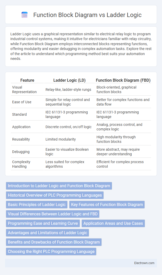
Table of Comparison
| Feature | Ladder Logic (LD) | Function Block Diagram (FBD) |
|---|---|---|
| Visual Representation | Relay-like, ladder-style rungs | Block-oriented, graphical function blocks |
| Ease of Use | Simple for relay control and sequential logic | Better for complex functions and data flow |
| Standard | IEC 61131-3 programming language | IEC 61131-3 programming language |
| Application | Discrete control, on/off logic | Analog, process control, and complex logic |
| Reusability | Limited modularity | High modularity through function blocks |
| Debugging | Easier to visualize Boolean logic | More abstract, may require deeper understanding |
| Complexity Handling | Less suited for complex algorithms | Efficient for complex process control |
Introduction to Ladder Logic and Function Block Diagram
Ladder Logic is a graphical programming language widely used in industrial automation, featuring symbols resembling electrical relay logic to design control systems. Function Block Diagram (FBD) uses interconnected blocks representing functions or operations, streamlining complex control processes by visually organizing logic components. Both languages enhance Programmable Logic Controller (PLC) programming by offering intuitive, visual approaches tailored for different engineering preferences and application needs.
Historical Overview of PLC Programming Languages
Ladder Logic, one of the earliest PLC programming languages, originated in the 1960s, designed to mimic electrical relay logic diagrams for ease of use by electricians and engineers. Function Block Diagram (FBD) emerged later as a graphical language focused on modular and reusable programming structures, enhancing the development of complex control systems. Understanding these historical developments helps you choose the most effective PLC programming language for industrial automation projects.
Basic Principles of Ladder Logic
Ladder Logic is a graphical programming language used primarily in industrial automation that represents electrical control circuits with symbols resembling relay logic diagrams. It operates on a rung-based structure where each rung consists of inputs, outputs, and logic operations executed sequentially to control machinery. Understanding the basic principles of Ladder Logic helps you design and troubleshoot control systems efficiently by visualizing process control flow and enabling easy implementation of timers, counters, and simple logic functions.
Key Features of Function Block Diagram
Function Block Diagram (FBD) features graphical programming with interconnected function blocks representing operations or control functions, making complex logic easier to visualize and manage. It supports modular design through reusable blocks, enhancing code organization and troubleshooting compared to Ladder Logic's relay-based approach. Your automation projects benefit from the intuitive layout and structured data handling that FBD offers for sophisticated control systems.
Visual Differences Between Ladder Logic and FBD
Ladder Logic features a schematic resembling electrical relay diagrams with rungs representing logical operations, making it visually intuitive for electricians and control engineers. Function Block Diagram (FBD) displays interconnected blocks, each representing a specific function or operation, linked by lines that indicate signal flow, emphasizing modularity and data processing. The clear visualization of control logic in Ladder Logic contrasts with FBD's focus on function-centric graphical programming, aiding different approaches to industrial automation design.
Programming Ease and Learning Curve
Ladder Logic offers an intuitive visual approach resembling electrical relay diagrams, making it easier for electricians and technicians with limited programming background to learn and implement quickly. Function Block Diagram (FBD) provides modular, reusable code blocks suited for complex control systems, but its abstract nature can introduce a steeper learning curve for beginners. The simplicity of Ladder Logic expedites basic automation programming, while FBD's structured layout benefits users seeking scalable and maintainable code in advanced applications.
Application Areas and Use Cases
Ladder Logic excels in industrial automation for programmable logic controllers (PLCs) frequently used in manufacturing assembly lines, motor control, and safety interlock systems due to its intuitive relay-based design. Function Block Diagram is preferred in process control industries, such as chemical and pharmaceutical plants, for complex signal processing, continuous control, and modular function blocks enabling reusable and scalable system configurations. Both languages support fault diagnosis and maintenance but differ in applicability where Ladder Logic targets discrete control tasks and Function Block Diagram suits process-intensive applications.
Advantages and Limitations of Ladder Logic
Ladder Logic offers intuitive visual representation and ease of use for those familiar with electrical relay logic, making it ideal for simple control systems and quick troubleshooting. Its limitations include reduced scalability and difficulty handling complex processes compared to Function Block Diagram, which better supports modular and reusable code structures. Your choice depends on whether straightforward design or advanced process control is prioritized.
Benefits and Drawbacks of Function Block Diagram
Function Block Diagram (FBD) offers a visual and intuitive approach to programming automation systems, enabling easier representation of complex logic through interconnected blocks. Its benefits include simplified debugging, modular design, and enhanced readability, which can improve efficiency in system development and maintenance. However, FBD can be less flexible for sequential operations compared to Ladder Logic, and its reliance on standardized blocks may limit customization for specialized tasks in your projects.
Choosing the Right PLC Programming Language
Choosing the right PLC programming language depends on application complexity and developer expertise, with Ladder Logic offering intuitive, relay-based visuals suitable for simple control tasks and maintenance by electricians. Function Block Diagram provides modular, reusable code blocks ideal for process automation requiring complex data handling and scalability. Evaluating project requirements and team skills ensures optimal efficiency and maintainability in automation systems.
Ladder Logic vs Function Block Diagram Infographic