Matched impedance ensures maximum power transfer and minimal signal reflection in your electronic circuits, optimizing performance and reducing interference. Understanding the differences between matched and unmatched impedance is crucial for designing efficient systems--read on to explore how proper impedance matching can enhance your applications.
Table of Comparison
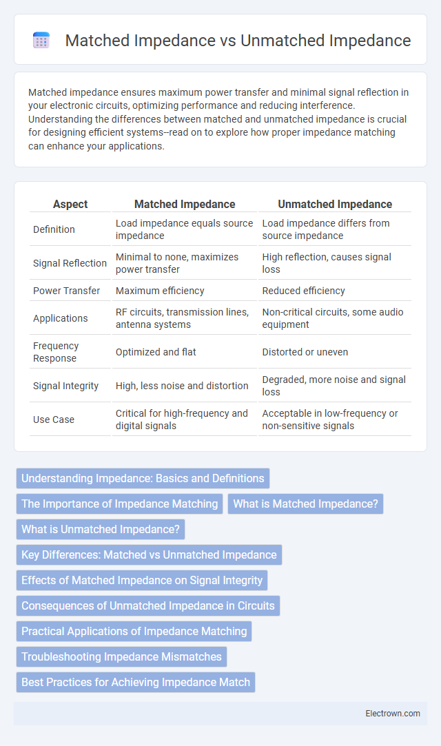
| Aspect | Matched Impedance | Unmatched Impedance |
|---|---|---|
| Definition | Load impedance equals source impedance | Load impedance differs from source impedance |
| Signal Reflection | Minimal to none, maximizes power transfer | High reflection, causes signal loss |
| Power Transfer | Maximum efficiency | Reduced efficiency |
| Applications | RF circuits, transmission lines, antenna systems | Non-critical circuits, some audio equipment |
| Frequency Response | Optimized and flat | Distorted or uneven |
| Signal Integrity | High, less noise and distortion | Degraded, more noise and signal loss |
| Use Case | Critical for high-frequency and digital signals | Acceptable in low-frequency or non-sensitive signals |
Understanding Impedance: Basics and Definitions
Impedance is the measure of opposition that a circuit presents to the flow of alternating current, combining resistance, inductance, and capacitance effects. Matched impedance occurs when the source and load impedances are equal, maximizing power transfer and minimizing signal reflections. Unmatched impedance results in signal loss, reflections, and potential distortion due to impedance mismatches between components.
The Importance of Impedance Matching
Impedance matching is crucial in electronic circuits and communication systems to maximize power transfer and minimize signal reflection, ensuring optimal performance and signal integrity. Matched impedance prevents energy loss and distortion, whereas unmatched impedance can cause signal degradation, increased noise, and potential damage to components. Understanding the importance of impedance matching allows you to design efficient systems with improved reliability and performance.
What is Matched Impedance?
Matched impedance occurs when the impedance of a load equals the impedance of the source or transmission line, maximizing power transfer and minimizing signal reflections. This condition is critical in high-frequency systems, RF circuits, and transmission lines to ensure signal integrity and optimal performance. Properly matched impedance reduces signal loss, standing waves, and distortion in communication and electronic devices.
What is Unmatched Impedance?
Unmatched impedance occurs when the impedance of a source, transmission line, or load does not match, causing signal reflections and power loss. This impedance mismatch results in standing waves along the transmission line, degrading signal integrity and reducing efficiency. Unmatched impedance is critical in RF and high-frequency circuits where precise impedance matching ensures maximum power transfer and minimal signal distortion.
Key Differences: Matched vs Unmatched Impedance
Matched impedance occurs when the source impedance equals the load impedance, maximizing power transfer and minimizing signal reflections in communication systems. Unmatched impedance results in a mismatch that causes signal reflection, power loss, and potential distortion, degrading performance in RF circuits and transmission lines. Key differences include signal integrity, power efficiency, and noise reduction, with matched impedance providing optimal conditions for signal transmission.
Effects of Matched Impedance on Signal Integrity
Matched impedance minimizes signal reflections and power loss, ensuring maximum signal transfer efficiency in high-frequency circuits. Your signal integrity improves significantly, reducing distortion and electromagnetic interference, which is critical for reliable data transmission. Unmatched impedance generates signal reflections and standing waves, leading to potential errors and degraded performance in communication systems.
Consequences of Unmatched Impedance in Circuits
Unmatched impedance in circuits causes significant signal reflections that degrade waveform integrity and result in increased signal loss. These reflections generate standing waves, which can lead to distortion, reduced signal power, and potential damage to circuit components due to impedance mismatch stress. Proper impedance matching is essential to ensure maximum power transfer, minimize electromagnetic interference, and maintain signal quality in high-frequency and RF circuits.
Practical Applications of Impedance Matching
Impedance matching is crucial in practical applications such as audio systems, radio frequency devices, and transmission lines to maximize signal transfer and minimize reflections. Matched impedance ensures optimal power delivery and reduces signal loss, enhancing the performance of antennas, amplifiers, and sensors. Your electronic design benefits from impedance matching by improving efficiency, signal integrity, and overall system reliability.
Troubleshooting Impedance Mismatches
Troubleshooting impedance mismatches involves measuring signal reflections using a time domain reflectometer (TDR) or a vector network analyzer (VNA) to identify points where the impedance deviates from the system's characteristic value, causing signal loss or distortion. Matched impedance ensures maximum power transfer and minimal signal reflection by aligning the load impedance with the source impedance, while unmatched impedance leads to reflections, standing waves, and reduced signal integrity. Correcting mismatches requires adjusting cable lengths, replacing faulty connectors, or impedance matching components like transformers or resistive pads to maintain signal quality.
Best Practices for Achieving Impedance Match
Achieving impedance match requires careful selection of transmission lines and components to minimize signal reflections and power loss. Utilizing impedance matching devices such as transformers, stubs, or tuners ensures that the source and load impedances are equal, optimizing signal integrity and system performance. Applying precise measurement tools like vector network analyzers during the design phase helps verify and adjust impedance values for the best signal transfer efficiency.
Matched impedance vs Unmatched impedance Infographic